CPSC 220, Fall 2012
Lab 2: Building Circuits with Logisim
In this lab, you will be working with Logisim, a free circuit simulation program. There is a copy in /classes/cs220. If you want to use it on your own computer, you can download a copy from http://ozark.hendrix.edu/~burch/logisim/.
To run Logisim, you can right-click the icon for logisim.jar in /classes/cs220 and select "Open With OpenJDK Java 6 Runtime". Alternatively, you can start it from the command line with the command java -jar /classes/cs220/logisim.jar.
Note that you can find an extensive "User Guide" and "Library Reference" in Logisim's "Help" menu. The "Library Reference" documents all the built-in circuit elements that are available in Logisim. The built-in circuit elements are listed in a component palette in the upper left section of the Logisim window. The most common are also available in the toolbar at the top of the window. For this lab, you are limited (with one exception) to using gates, wires, inputs, outputs, and splitters. You will be building some circuits that are equivalent to built-in Logicsim circuits, but you should build them yourself out of simple components.
This lab is due next Tuesday, at the start of next week's lab. You should create one Logisim file, containing all the circuits that you are asked to build in this lab. You should copy the circuit file that you create into your homework folder in /classes/cs220/homework.
Exercise 1: XOR gate
For this exercise, you should build an XOR gate out of AND, OR, and NOT gates. Note that Logisim already has an XOR gate, but you should build your own. (This is essentially the "Tutorial" in the "Help" menu of the program, except that I am asking you to give a name to the circuit that you create.)
In Logisim, you can build new circuits, and then use the circuits as components in other circuits. This allows you to build up complex circuits from simpler circuits (just like you make complex programs from simpler subroutines). To create a new circuit, use the "Add Circuit" command in the "Project" menu. You will be asked for a circuit name. Enter XOR as the name of the new circuit for the first exercise. The circuit that you have created is added to the palette of circuit elements in the upper left portion of the window, under the name of the file that you are working in (probably "Untitled" at present). To view and edit a circuit that you have created, double-click its name in the list.
Logisim has three mouse tools, which have different functions. They are shown as icons on the left end of the toolbar. The right end of the toolbar shows five common circuit elements, input, output, NOT gate, AND gate, and OR gate:

The "poke" tool, which looks like a pointing hand, is for poking inputs to turn them on and off. The "edit/select" tool, which looks like an arrow, allows you to add components to a circuit and to select existing elements in the circuit; this is the default tool. The "text" tool, which looks like an "A", is used to add strings of text to a circuit; just click with the text tool, and type something.
To add a component to the circuit that you are editing, click the component in the toolbar or in the palette of circuit elements (with the arrow tool). Move the mouse to the place where you want to place the component and click again. (Do not drag the component. Click it and release the mouse, move the mouse, and click again.) For example, to add an AND gate, click the AND gate in the toolbar or in the component palette, move to the position where you want the AND gate, and click again.
You can also use the arrow tool to add wires to the circuit. When the arrow tool is over a point where you can start drawing a wire, Logisim draws a small green circle around that point. Click and drag to draw the wire. In general, things that look like they are connected are in fact connected.
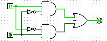
There are several ways to make an XOR circuit from AND, OR, and NOT gates. We looked at one in class that corresponds to the logical expression (A | B) & ~(A & B). Here is another way to do it, corresponding to (A & ~B) | (B & ~A):
Build an XOR circuit. Test that your circuit works, using the poke tool. Try all four combinations of input, and make sure that the outputs are correct.
Note: If you click on a component of the circuit with the edit/select tool, it will be selected. You can drag it, delete it, copy-and-paste it, and edit its properties. The properties of the selected component are shown in the lower left section of the Logisim window, and you can change a property by clicking its value. For example, you need to do this if you want a gate to face in a different direction. If you click and drag on the circuit to make a box around some components, all the components in the box are selected; you can then move, delete, or copy-and-paste all the selected components as a group.
You probably want to save your circuit at this point. Give it a name such as lab2.circ. (The name should end with ".circ".) You should save your circuits frequently while you are working.
Exercise 2: Adder
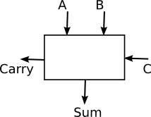
For the next exercise, add another circuit using "Add Circuit" in the "Project" menu, and name it "Adder". You will create an adder that can add three input bits and produce a sum bit and a carry bit as output. In class, we saw how to make an adder from two half-adders. You might already have read about an alternative design in the textbook. You can build it any way you want, but it's useful to arrange the inputs and outputs as shown here:
If you use XOR gates, you can use either the one that you built for Exercise 1 or the one that is built into Logisim.
Exercise 3: Four-bit Adder
For the third exercise, add another circuit, using the name "Add-4". The purpose of the circuit is to take two four-bit numbers and a one-bit carry-in and to produce a four-bit sum and a one-bit carry-out as output. We saw in class how to construct a four-bit adder from four single-bit adders. User four copies of the Adder that you created for exercise 2.
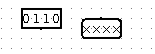 In Logisim, it is possible to have multi-bit inputs, multi-bit outputs,
and wires that carry multiple bits of data. To make a four-bit input, for
example, add an input to your circuit, then change the value of the
"Data Bits" property of the input to 4 (in the properties list in the lower
left section of the window). A four-bit input and a four-bit output are shown
at the right. The poke tool has been used to change the value of the input
to 0110. The values of the output bits are undefined. You should use
four-bit inputs and outputs for your adder.
In Logisim, it is possible to have multi-bit inputs, multi-bit outputs,
and wires that carry multiple bits of data. To make a four-bit input, for
example, add an input to your circuit, then change the value of the
"Data Bits" property of the input to 4 (in the properties list in the lower
left section of the window). A four-bit input and a four-bit output are shown
at the right. The poke tool has been used to change the value of the input
to 0110. The values of the output bits are undefined. You should use
four-bit inputs and outputs for your adder.
 But you need single-bit wires to feed into your individual Adder circuits.
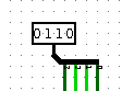
For that, you need a "Splitter". A Splitter splits a multi-bit bundle of wires into
smaller bundles of wires or into individual wires. You can find "Splitter"
in the "Wiring" section of the component palette. The picture at left shows
a splitter connected to the wire bundle coming out of a 4-bit input; it splits
that bundle into four individual wires. In this case, the properties of the
splitter have been set so that it is "Facing" South, has a "Bit Width In" of
4, and a "Fan Out" of 4. Each of the outputs is a single wire that can be
connected, for example, to an input of an Adder.
But you need single-bit wires to feed into your individual Adder circuits.
For that, you need a "Splitter". A Splitter splits a multi-bit bundle of wires into
smaller bundles of wires or into individual wires. You can find "Splitter"
in the "Wiring" section of the component palette. The picture at left shows
a splitter connected to the wire bundle coming out of a 4-bit input; it splits
that bundle into four individual wires. In this case, the properties of the
splitter have been set so that it is "Facing" South, has a "Bit Width In" of
4, and a "Fan Out" of 4. Each of the outputs is a single wire that can be
connected, for example, to an input of an Adder.
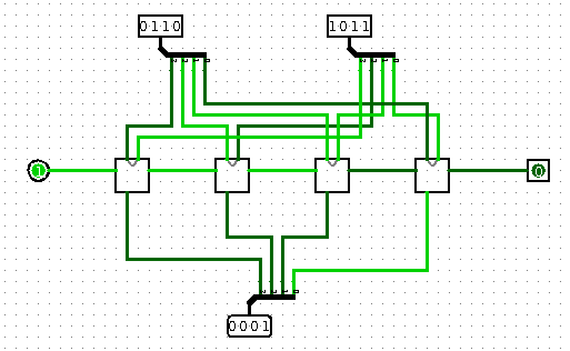
The Add-4 circuit that you build should look approximately as follows. It is shown here adding the number 0110 to 1011, with a carry-in of zero:
Exercise 4: Sixteen-bit Adder
Four-bit numbers are pretty limited. For your next exercise, add another circuit, named "Add-16". The circuit can be built from four copies of your Add-4 circuit in much that same way that you build Add-4 from 4 copies of adder. However, you will need 16-bit inputs and outputs and splitters that join a bundle of 16 wires to 4 bundles of 4 wires each.
Exercise 5: Sixteen-bit AND
Just as it is possible to build a circuit to compute A+B for two 16 bit numbers A and B, it is possible to build a circuit to compute the bitwise logical operation A&B. In fact, it's very simple.
For this exercise, build a circuit named AND-16 that computes the bitwise AND of two 16-bit inputs. It can be build using 16 AND gates, but you might want to build it in two stages, as we did for the 16-bit adder. Your circuit should have two 16-bit inputs and one 16-bit output.
Exercise 6: Tiny ALU
For this exercise, you should add a circuit named TinyALU to hold your work.
An ALU (arithmetic-logic unit) in a computer performs arithmetic and logical operations on numbers. The same ALU can perform several different operations, and it has control wire inputs to tell it which operation to perform.
For the final exercise of the lab, you should build a very small ALU that does just two operations: addition and bitwise AND. It should operate on 16-bit numbers, with two 16-bit inputs and one 16-bit output. It should have one control wire input that tells it which operation to output; the output is the result of one operation when the control wire is on, and it is the result of the other operation when the control wire is off. (Your circuit could also have a one-bit output representing the carry from the addition, if the operation that it performs is addition.)
The funny thing about an ALU is that it actually performs all of its operations in all cases. The control wires just determine which of the results gets to the output. If you think about it, what you need here is a multiplexor. In this case, you can use the Multiplexor component that is built into Logisim; you will find it in the "Plexors" section of the component palette. (Alternatively, if you want, you can build the multiplexor that you need from basic gates. Would there be extra credit for this? Who knows.)
Don't forget to test all of your circuits to make sure that they are working correctly before you turn in your file!