CPSC 220, Fall 2018
Lab 6: Sequential Circuits
For this lab, you will work with the Logisim program that you used in the previous lab. Last week, you built combinational circuits. This week, you will build sequential circuits. In the first four exercises, you will build a D-latch, a D-flip-flop, a basic eight-bit register, and an 8-bit register that can take its input from several different sources. The last exercise, which is more ambitious, asks you to create a sequential multiplier. The multiplier will compute the product of two 16 bit numbers using a series of additions, where the process is driven by a clock.
The lab is due next Thursday. You should create a file named lab6.circ containing all of the circuits that you create for this lab. To submit your work, copy your lab6.circ file into your homework folder in /classes/cs220/homework.
Circuit #1: D-Latch
We covered D-latches and D-flip-flops in class. You will start by making a D-latch circuit for this exercise. Then, for the next exercise, you will use two D-latches to build a D-flip-flop.
Recall that a D-latch has two inputs, data-in and clock/load. It has one output, data-out. The operation is this: As long as clock is ON, the value of data-out is that same as data-in. When the clock/load input is OFF, data-out does not change. Basically, the circuit is a 1-bit memory that stores the value that is on the data-in wire at the time that the clock input is turned off.
Start up Logisim and add a new circuit, named D-latch, to the project. Make an R-S latch in the circuit, using either of the two designs from class. (One design uses two NOR gates. The other uses an OR gate, and AND gate, and a NOT gate.) Recall that the two versions look like this; use the one you like:
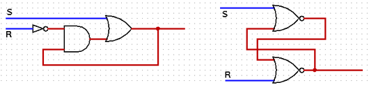
You can then add the extra circuitry that you need for a D-latch: Two AND gates and a NOT gate. The extra circuitry is there to make sure that set is only turned on when both data-in and clock/load are on. And reset should be on only when data-in is off and clock/load is on. Be sure to test your circuit to make sure that it works correctly. (Note: The wire that I am calling clock/load is meant to be controlled, at least partly, by the clock. However, for now, we will just use it to load data by hand.)
Circuit #2: D-Flip-Flop
Add a second new circuit, named D-flip-flop, to the project. This circuit also has data-in and clock/load inputs and a data-out output, but now the output can only change on the falling edge of the clock cycle, that is, at the moment that the clock is turned off.
The circuit is very simple to build, as we saw in class. (Add two copies of your D-latch circuit, one to be the "master" and one to be the "slave." The master's output connects to the slave's input. The flip-flop's data-in connects to the data-in of the master, while the flip-flop's data-out connects to the data-out of the slave. The flip-flop's clock/load input connects directly to one of the two latches, and through a NOT gate to the other latch. Where you put the NOT gate determines whether the flip-flop loads on the rising clock edge or the falling clock edge. Again, test your circuit to make sure that it works!)
Circuit #3: Basic 8-bit Register
Next, add a new circuit to your project named Basic Register, and construct an 8-bit register. The register should have an 8-bit data-in input and an 8-bit data-out output. It has a one-bit clock/load input. It can be built using 8 D-flip-flops.
Circuit #4: Multi-input Register
A register in a CPU can often take its input from several different sources, depending on the instruction that is being executed. When that is possible, of course, there must be "select" control wires that specify which of the inputs is actually stored into the register. One possible design is to use a standard multiplexer that determines the input source: All the possible inputs are inputs to the multiplexer, and the output of the multiplexer is the selected input. The multiplexer's output connects to the register's data-in. (An alternative to using a multiplexer is to design your own control circuitry, which might be more efficient in this case; however, I suggest using a standard Logisim multiplexer component.)
Add another new circuit, named "Multi-input register," to the project. Add a copy of your 8-bit register to the circuit, to use as a basis for the new circuit. The register will have three possible input sources: A data-in input, coming from outside the circuit; an 8-bit constant input, set equal to zero; and the output of an Adder that increments the register by adding 1 to the current value in the register. Thus, the circuit design includes the components shown here:
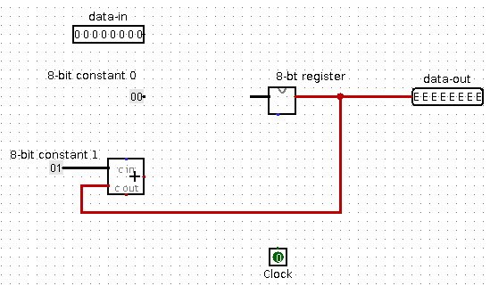
The red error lines should go away once you complete the circuit and turn the clock input on and off. Note that if you have problems with this, you can substitute Logisim's Register component for your own register.
To complete the circuit, add a multiplexer with 8 data bits and 2 select bits. Add a two-bit input to connect to the select input of the multiplexer. And then finish the wiring. Since the multiplexer has four inputs and there are only three possible inputs for the register, you can connect one of the possible inputs to two multiplexer inputs. For example, select bits equal to 00 or 01 could load the register from the data-in input, select bits equal to 10 could load the register with constant zero, and select bits equal to 11 could increment the value in the register.
(Alternatively, select values 00 could mean to leave the number in the register unchanged. You could implement this by adding some circuitry to stop the clock signal from getting through to the register when the select inputs are 00.)
Circuit #5: Sequential Multiplier
The final circuit for this lab will be the most complicated you have worked on so far. The goal is to multiply two unsigned 16-bit numbers to get a 32-bit product. It is possible to build a combinational circuit that will do that. A version was demonstrated in class that uses fifteen 32-bit adders. However, you will build a sequential multiplier that uses just one 32-bit adder. The circuit is driven by a clock. It will compute the sum as a series of up to sixteen additions. This is the first time that you will use a clock to program a computation that "runs itself."
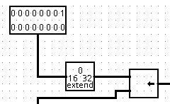 The circuit will have two 16 bit inputs, representing the numbers to be
multiplied. The numbers need to be zero-extended to 32 bits. Logisim
has a "Bit Extender" component, under "Wiring," that will do that.
In the algorithm, one of numbers is logical-right-shifted while the
other is logical-left-shifted. The "Shifter" component, under "Arithmetic,"
can do that. So, the two inputs need to be wired up similarly to the
diagram shown at the right.
The circuit will have two 16 bit inputs, representing the numbers to be
multiplied. The numbers need to be zero-extended to 32 bits. Logisim
has a "Bit Extender" component, under "Wiring," that will do that.
In the algorithm, one of numbers is logical-right-shifted while the
other is logical-left-shifted. The "Shifter" component, under "Arithmetic,"
can do that. So, the two inputs need to be wired up similarly to the
diagram shown at the right.
 For the N-th step of the computation, the inputs need to be shifted
left or right by N bits. The number of bits to shift can be specified
by a counter that counts the steps in the computation.
A Logisim "Counter" register, under "Memory,"
holds a number that can be incremented by turning a clock input on and off.
A Counter is shown at the left. The clock input is on the bottom left.
The input on the bottom right sets the number in the register to zero.
(It does this "asynchronously"; that is, the input is not clocked and
as long as it is on, the number in the register is pinned to zero.)
The number that is currently in the Counter is the output on the right
side of the Counter. There are three
inputs on the left side that are not needed for this application.
The counter must be able to count at least up to 16, or 0x10 in hexadecimal,
which is the maximum amount of shifting that is needed to multiply
two unsigned numbers.
For the N-th step of the computation, the inputs need to be shifted
left or right by N bits. The number of bits to shift can be specified
by a counter that counts the steps in the computation.
A Logisim "Counter" register, under "Memory,"
holds a number that can be incremented by turning a clock input on and off.
A Counter is shown at the left. The clock input is on the bottom left.
The input on the bottom right sets the number in the register to zero.
(It does this "asynchronously"; that is, the input is not clocked and
as long as it is on, the number in the register is pinned to zero.)
The number that is currently in the Counter is the output on the right
side of the Counter. There are three
inputs on the left side that are not needed for this application.
The counter must be able to count at least up to 16, or 0x10 in hexadecimal,
which is the maximum amount of shifting that is needed to multiply
two unsigned numbers.
The circuit will need a 32-bit adder, and a register to accumulate the answer. You should use Logisim's versions of these components. The adder adds the output of the register to the next term in the sum.
You should add a 1-bit "Load-zero" input that connects to the load-zero inputs of the "Counter" and the 32-bit register. It will be necessary to turn this input on and off before starting a new computation.
You should also add a "Clock," which you can find under "Wiring" in Logisim. The clock's output connects to the clock input of the counter and to the clock input of the 32-bit register. You can use the poke tool to turn the clock on and off by hand. To make it run by itself, turn on the "Ticks Enabled" option in the "Simulate" menu. The "Tick Frequency" submenu in the "Simulate" menu can be used to set the speed at which the clock ticks.
You should finish building the circuit to carry out the multiplication algorithm. Recall that at each step, you need to test the low-order bit of the right-shifted input. If that low-order bit is one, then the left-shifted input must be added to the current value in the 32-bit register; otherwise, zero should be added to the current value in the register. You can test the computation by turning the clock on and off by hand. It might be useful to connect "Probes" to some of the output wires. A Probe displays the current value on the wire to which it is connected; it has no other effect on the circuit.
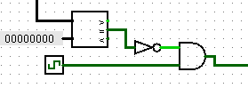
But we want the computation to be able to run itself, using a ticking clock. That computation needs to end once the sum has been computed. One way to end it is to stop the clock when the right-shifted input becomes equal to zero, since once that happens, there are no more terms that need to be added to the answer. There is no way to actually stop the clock, but you can stop the clock's output from getting through to the registers. There are several ways to do that. For example, you could use a "Comparator" (under "Arithmetic" in Logisim") and some gates to block the clock's output when the right-shifted input value is zero:
Don't forget to test your circuit!