CPSC 324, Fall 2002
Lab 10: Blender Particle Systems
BY NOW, YOU have some idea of the power of Blender. Today, you will look at one of its most interesting advanced features: particle systems. A particle system is essentially a bunch of free-moving vertices that are emitted by a mesh object. The particles have a finite lifetime. They have an initial velocity and can be affected by forces that simulate things like gravity and friction. If you assign a halo material to the mesh that emits the particles, then each particle will be a halo. By setting and animating various halo properties, you can make the particle system take on the appearance of things as varied as fog and fireworks. It is also possible to place an object on each particle. The objects are all duplicates of one model object, and so are identical. This might be used, for example, to model a school of fish.
Although the lab is mostly devoted to particle systems, there is also a short section on another advanced feature: environment maps. An environment map can make an object look like it is reflecting its environment. At the end of the lab you will find, for your information, a few notes about other features of Blender. These are not a required part of the lab, but you might find them useful if you continue to work with Blender.
Exercises: For this lab, you should create one animation that uses a particle system and one still image that uses an environment map. Save the animation in AVI JPEG format and put a link to the animation on your Web page, along with a description of how it uses particles. Also add the still image to your web page. You can, if you like, use an animated environment map in your animation (although this will probably take a lot of rendering time). In that case, one of the frames from your animation can serve as your still image.
Particle Systems
 Particles can be emitted from any mesh object, but most often a plane or
mesh circle is used. It's easy to get a plane to emit particles in
a direction perpendicular to the plane, and it's easy get a mesh circle
to emit them radially outward from the center of the circle. In the
picture, particles have been emitted moving upwards from the plane. The
particles also have a small random amount added to their velocities, which
makes them spread out as they move. Note that in the default setting,
which is used here, particles are emitted only from the vertices
of the mesh. Often, you will want to decrease the size of the
emitter so that it looks like all the particles are coming from
about the same place.
Particles can be emitted from any mesh object, but most often a plane or
mesh circle is used. It's easy to get a plane to emit particles in
a direction perpendicular to the plane, and it's easy get a mesh circle
to emit them radially outward from the center of the circle. In the
picture, particles have been emitted moving upwards from the plane. The
particles also have a small random amount added to their velocities, which
makes them spread out as they move. Note that in the default setting,
which is used here, particles are emitted only from the vertices
of the mesh. Often, you will want to decrease the size of the
emitter so that it looks like all the particles are coming from
about the same place.
In order to understand particles, you have to work with them a bit. Start with a plane object, as in Blender's default start-up configuration, go into camera view (Keypad-0), and move the plane down towards the bottom of the view. To add a particle system to the plane, make sure the plane is selected and go to the Animation buttons (F7). Click on the button named "New Effect" in the center of the Edit button window. Then switch the pop-up menu, which initially says "Build", to "Particles". A large number of buttons appear for controlling the particle system, as shown below. The first three buttons, "Total", "Sta", and "End" say that there will be 1000 particles in the particle system. The plane will start emitting them in frame number 1 and will stop in frame number 100. (Thus, 10 particles will be emitted in each frame.) The next button, "Life", gives the lifetime of the particles. That is, each particle lives for 50 frames after it is emitted and then disappears. The "Keys" button controls the number of key frames that Blender creates for controlling the particle animation -- more keys might give a smoother animation. Leave these buttons at their default settings for now. The second row of buttons is used only for multi-generation particle systems, which are discussed later on this page.
The Remaining four rows of buttons are used to control the motion of the particles. If you leave them at their default settings, the particles will never move away from the position where they are born. (Even this might be OK if the object itself is moving.) The "RandLife" button can add some randomness to the lifetime of the particles. Turing "Face" on causes the particles to be emitted from polygon faces rather than just from vertices. "Bspline" should make the motion smoother (and I don't know why you would ever want to leave it off). The "Vect" button assigns a vector to each particle which points in the direction the particle is moving. This vector will affect objects attached to the particle so that they change orientation as they move. You might need this, for example, if you were animating a school of fish, to orient them along the line of motion.
The remaining buttons affect the speed of the particles. "Norm", "Ob", "Rand" affect their initial velocities. "Norm" makes a particle move away from its emitter, in the direction of the normal vector. If the emitter is moving, "Ob" tells how much of the object's velocity is transferred to the particle, making it move in the same direction as the object. "Rand" adds some extra speed in a random direction. Try these out on the plane. If "Norm" is positive and "Rand" is zero, the particles will move straight up from the plane. (To see the animation easily, go to frame 1 (Shift-Left-Arrow), then hold down the right arrow key.) Now if you change "Rand" to a positive value, you will get a picture more like the one shown above. To see the effect of "Ob", you will have to animate the plane: Make it move from left to right between frames 0 and 100.
The "Damp" button adds friction. That is , it gives the rate at which moving particles slow down. The "X", "Y", and "Z" Force buttons apply a force to each particle that that will gradually accelerate it in a given direction. For example, a negative "Z" force will act like gravity, pulling the particles downwards. An "X" force will act something like wind, blowing the particles horizontally. (If "Tex" is non-zero, the velocity can be affected by a texture, which can add effects such as turbulence, but I haven't tried this.)
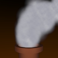
You should try some of the velocity controls. For example, You can make a "fountain" if you use a negative "Z" force along with "Norm", "Rand", and perhaps "Damp". Try a moving emitter with high values for "Ob" and "Damp" and perhaps a negative "Z" force -- smoke coming out of a smokestack might behave like this.
Halos and Objects for Particle Systems
 The little white particles that you see in the 3D window are not
visible in a rendered image. However, if you add a Halo material to
the emitter, then each particle will appear as a halo in
the rendered image. You can get various effects by using
different settings for the halo properties. The "smoke" shown in
this image is a particle system with relatively few particles and
rather large halos. A Cloud texture is used as a HaloTex on the
halos, to give each halo some variation in color. The texture just
uses two slightly different shades of gray. The animated version of
this is pretty effective. See smoke.avi (950K).
The Blender file for this is /home/cs441/lab10/smoke.blend.
The little white particles that you see in the 3D window are not
visible in a rendered image. However, if you add a Halo material to
the emitter, then each particle will appear as a halo in
the rendered image. You can get various effects by using
different settings for the halo properties. The "smoke" shown in
this image is a particle system with relatively few particles and
rather large halos. A Cloud texture is used as a HaloTex on the
halos, to give each halo some variation in color. The texture just
uses two slightly different shades of gray. The animated version of
this is pretty effective. See smoke.avi (950K).
The Blender file for this is /home/cs441/lab10/smoke.blend.
This example uses material animation to improve the smoke effect. As each particle ages, it gets smaller. This is accomplished by inserting animation keys for the "HaloSize" material property. (When you hit the "I" key in the Material button window, this property is listed as "HaSize" in the menu.) You could also animate the color or transparency of the halos. Note that the halo on each particle is animated separately, over the lifetime of the particle. For halo animations, the frame number has a peculiar meaning: Frame 1 corresponds to the beginning of the particle's life, and frame number 100 corresponds to the end. This is true no matter what the actual lifetime of the particle.
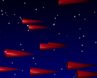 As an alternative to halos, it is possible to place a duplicate of
an object at each particle. In the image, particles are emitted from
a large vertical plane located at the left. There is a red cone at
the position of each particle. This is not very difficult to do:
Create the object that you want to duplicate. Make that object a
child of the emitter. (Right-click the object, shift-right-click the
emitter, press CONTROL-P, and confirm that you want to "Make Parent".)
Now, select the emitter. Go to the Animation buttons (F9). Find
the button named "DupliVerts" and click it. You will see a duplicate of the object
at each particle. (In fact, DupliVerts can be used on any mesh,
not just on meshes being used as particle emitters -- one copy of the
duplicated object is made for each vertex of the mesh.)
As an alternative to halos, it is possible to place a duplicate of
an object at each particle. In the image, particles are emitted from
a large vertical plane located at the left. There is a red cone at
the position of each particle. This is not very difficult to do:
Create the object that you want to duplicate. Make that object a
child of the emitter. (Right-click the object, shift-right-click the
emitter, press CONTROL-P, and confirm that you want to "Make Parent".)
Now, select the emitter. Go to the Animation buttons (F9). Find
the button named "DupliVerts" and click it. You will see a duplicate of the object
at each particle. (In fact, DupliVerts can be used on any mesh,
not just on meshes being used as particle emitters -- one copy of the
duplicated object is made for each vertex of the mesh.)
An animation of the flying cones can be found in cones.avi (1.7M). In an alternative version, cones_with_x_force.avi (1.3M), I used a small initial velocity with a large force in the X direction to make it look like the cones were appearing on the left then accelerating rapidly to the right. You can find the blender file in /home/cs324/lab10/cones.blend.
For the cones example, I subdivided the emitting plane several times so that cones would be emitted from more points on the plane. However, I still had the problem that the cones were emitted in a very regular pattern. In a particle system, the vertices of a mesh take turns emitting particles. If the vertices are ordered in a regular pattern, then the particles are emitted in the same pattern. To fix this, I randomized the order of the vertices: Select the mesh, go into edit mode, and select all the vertices. Go to the Edit buttons (F9). Find the button named "Hash" and click it.
FYI: Generations of Particles
 A more advanced aspect of particle systems is the use of multiple generations
of particles. (You are not required to know how this works.)
When a particle reaches the end of its lifetime, it can give birth to
one or more new particles. It is possible to assign a different material to
each generation. You can even have a third generation. The picture is from a particle
animation that uses two generations. The emitter in this example is a mesh circle that
moves along a curve, dropping off particles. About 1/4 of these particles will bloom
at the ends of their lifetimes into another generation of particles. The new particles
are more orange than the originals. All the particles have a short lifetime and decrease
rapidly in size. The animation can be found in sparkles.avi (400K),
and the Blender file is /home/cs324/lab10/sparkles.blend.
A more advanced aspect of particle systems is the use of multiple generations
of particles. (You are not required to know how this works.)
When a particle reaches the end of its lifetime, it can give birth to
one or more new particles. It is possible to assign a different material to
each generation. You can even have a third generation. The picture is from a particle
animation that uses two generations. The emitter in this example is a mesh circle that
moves along a curve, dropping off particles. About 1/4 of these particles will bloom
at the ends of their lifetimes into another generation of particles. The new particles
are more orange than the originals. All the particles have a short lifetime and decrease
rapidly in size. The animation can be found in sparkles.avi (400K),
and the Blender file is /home/cs324/lab10/sparkles.blend.
The row of buttons labeled "CurMul", "Mat", "Mult", "Life", and "Child" control multiple generations of particles. "CurMul" tells which generation the other buttons are talking about. "Mat" determines which material is used for that generation (but if you want to know how to use multiple materials, you will have to look it up). "Mult" tells what fraction of particles in this generation give birth to new particles. Setting this to a value greater than zero gives a multi-generation particle system. The "Life" button gives the lifetime of the child particles, and the "Child" button gives the number of children generated. When you use multiple generations, the "Tot" button gives the total number of particles in the system, including children.
As an example using a plane as an emitter, set the "Mult" button to 1 and the number of children to 49. With "Tot" set to 1000, this will give exactly 20 first generation particles. Set both "Norm" and "Rand" to be positive, and use a negative "Z" force. Decrease the lifetimes of the particles. The particle animation will look something like fireworks, with each original particle blooming into 49 new particles. An animation that uses this technique can be found in firework.avi (529K).
Environment Maps
 Environment maps are used to simulate reflection of the scene in a shiny object. Blender does
environment mapping by making six images of the scene -- one view in each direction from the
position of a specified reference object (or, more precisely, from the center point of the
reference object.) These scenes are then used as a texture on the
reflective object. In the image at the right, an environment map is applied to the sphere.
In the textured eggs image from the previous lab,
an environment map is applied to the plane on which the eggs are standing.
Environment maps are computed automatically in blender, once the parameters are set up.
If you are doing an animation, you can even have blender compute a new environment map
for each scene. The blender file for this image is /home/cs324/lab10/env.blend.
Environment maps are used to simulate reflection of the scene in a shiny object. Blender does
environment mapping by making six images of the scene -- one view in each direction from the
position of a specified reference object (or, more precisely, from the center point of the
reference object.) These scenes are then used as a texture on the
reflective object. In the image at the right, an environment map is applied to the sphere.
In the textured eggs image from the previous lab,
an environment map is applied to the plane on which the eggs are standing.
Environment maps are computed automatically in blender, once the parameters are set up.
If you are doing an animation, you can even have blender compute a new environment map
for each scene. The blender file for this image is /home/cs324/lab10/env.blend.
For a typical curved solid object like a sphere, you can use the object itself as the reference object. This will not give a geometrically perfect result, but it will probably look good enough. To use an environment map on a sphere, for example:
- Select the sphere, make sure it has a material, go to the Texture Buttons, add a new texture to the sphere, and set the type of the texture to "EnvMap". You will see the Environment Map controls, which are shown below.
- In the button labeled "Ob:", enter the name of the sphere. (The name is probably "Sphere" if it is the only sphere in the scene. To find the name of an object, select the object and go to the Edit buttons (F9). The name is listed in a button labeled "OB:name" at the top of the Buttons window. Click this button if you want to change the name.)
- In the environment map controls, you will probably want to increase the "CubeRes" to 250 or more. This determines the size of the images created for the environment map. If it's too small, the reflection will be blurry.
- You have to go back to the Material Buttons and make some changes. Change the texture coordinates from the default "Orco" to "Refl". For the texture mode at the right end of the Material buttons, turn off the default "Col" and turn on "Cmir". If you render now, the sphere should look like a perfectly reflective mirror.
- To blend the environment map into the sphere's material, rather than replacing it, you can turn down the value on the "Col" slider at the bottom right of the Material Buttons.
- If you edit the scene, a new environment map will not be computed automatically. To force a new computation, go to the Texture Buttons and click the "Free Data" button in the environment map controls. To automatically recompute an environment map for each frame of an animation, click the "Anim" button.

The procedure for environment mapping a plane is the similar, except that you will not get good results using the plane itself as the reference object. Instead, you should use an Empty as the reference object and position it on the other side of the plane from the camera. Ideally, it should be at the exact position of the reflection of the camera in the plane (this would make the direct view from the reference point be the same as the reflected view from the camera). You can try to judge the position of the Empty reference object by eye, but this procedure below tells you how to get it exactly right if you want to be picky:
- Choose a view in which the plane is perpendicular to the screen, so you see it edge-on.
- Select the camera by right-clicking on it. Hit Shift-S (the "snap" command), and choose to snap "Curs->Sel" to snap the 3D cursor to the camera position.
- Add an empty object to the scene. It appears at the camera position.
- Select the plane by right-clicking on it. Hit Shift-S and choose "Curs->Sel". The cursor jumps to the plane.
 Set the reference point for scaling to be the cursor, rather than the center of
the object. To do this click the small button in the 3D window header shown at the right.
Set the reference point for scaling to be the cursor, rather than the center of
the object. To do this click the small button in the 3D window header shown at the right.
- Select the empty object by right-clicking it. Without touching the mouse, hit the "S" key to start scaling, the "Y" key to reflect the empty through the plane, and the "Return" key to finish the scaling. The empty object should now be exactly on the opposite side of the plane from the camera.
- Use the Empty as the reference object by entering its name (probably "Empty") in the "Ob:" button in the environment map controls.
There is a problem with using the Empty as the reference object instead of the plane: The plane will be part of the reflected environment! You have to tell the program to not render the plane as part of the environment. This is what the "Don't render layer" part of the environment map controls is for. Move the plane to layer 2 and select layer 2 in the "Don't render layer" buttons. Since you do want the plane to be in the final image, you need to set two layers to be displayed in the image and in the 3D Window. Do this by shift-clicking the appropriate layer button in the 3D window's header (or simply by hitting CONTROL-SHIFT-2).
Once this is done, you can proceed as above for the sphere: Set the appropriate values in the Materials buttons and render the image.
FYI: Yet More Features
We are very far from covering all of Blender, but here are a few last words about some features that might interest you:
Changing cameras -- You can add an extra camera to the world, but how do you use it? I've finally found the command for doing this: Select the camera that you want to use for viewing. Hold down the Control key and hit the Keypad-0 key. This will switch to the camera view from the selected camera, and that camera will now be used for rendering.
Camera controls -- Since you know that projection in OpenGL can be either perspective or orthographic, and since there is always a near and a far clipping distance, you might wonder where this is in Blender. Just select a camera and go to the Edit buttons. The Edit buttons for a camera allow you to select the projection type and to set the near and far clipping distances (called "ClipSta" and "ClipEnd" in Blender). The default clipping distances are probably OK for most scenes that you will create, but if you make a very large scene, you might have to increase ClipEnd.
Parenting -- We have made objects parents of other objects for various reasons, but you haven't seen the primary reason for parenting. If one object is a child of another object, then transformations that are applied to the parent are automatically applied to the child. However, transformations can also be applied to the child separately. For example, if you model the a car and make the wheels children of the body, then when you move the body the wheels move along with it. However, you can also apply rotations to the wheels, and they will rotate while they move along with the car.
Scenes -- A single blender file can hold several scenes. These scenes can be views of the same world, they can be completely separate, or they can share some objects. This is especially useful if you are using the sequencer to combine scenes. You might do a new scene to create titles for your animation. You might do two views of the same world through different cameras. You can also set different scenes to animate different ranges of frames. To create a new scene, look for the "SCE:xxxx" button at the top of the screen. Next to this is the pop-up menu (marked with a small rectangle) that you use to change from one scene to another and to create new scenes. If you choose "Add New" from this menu, you will get a new menu with four choices: "Empty", "Link Objects", "Link ObjData" and "Full Copy". "Empty" makes a new empty scene. "Full Copy" makes a copy of the current scene. The other two options make copies in which some data is shared between the two scenes. If you choose "Link Objects" you essentially get a new view of the same world: Moving an object in one scene will also move it in the other. (However, you can then add new objects to each scene that don't appear in the other scene.) "Link ObjData" copies part of the data for objects: If you move an object in one scene, it does not move in anther. However, if you change its vertex data in edit mode, it changes in both scenes.
DispView -- This is a small thing that I should have mentioned earlier. If you go to the Render buttons (F12) and look in the lower left corner, you will see a pair of buttons "DispView" and "DispWin". These control where rendered images are displayed. When "DispWin" is selected (the default), a separate window is used. As you have noticed, this window can be a pain. If you switch to "DispView", the rendered image is drawn in the 3D window so you don't have to fool around with another window. One disadvantage is that you don't see the rendered image at its true size.