Today's lab, after a short side trip on materials, is mostly about animation in blender. The whole lab follows up on the demonstration that I did in class last Thursday.
The material that you produce for this lab should be posted by Tuesday of next week. It should include a dramatic image that uses transparency, a few still frames from an animation, and a link to a short animation in MPEG format. (The stills and MPEG can be the same animation, if you want.) Your animation should use at least one of the advanced features discussed in this lab: tracking, path animation, or particle systems.
There are several sample blender files available for the examples mentioned in this lab. You can find them in the folder "blender files for lab 5" in the "cpsc324" folder on the "N" drive.
Transparency and Halos
Blender's basic material buttons give you control over the diffuse, specular, and ambient colors and the "shininess" of an object. You can change the basic color and the specular color using the RGB sliders. (You can change to the HSV system by clicking the HSV button to the left of the color sliders.) Usually, the specular color is white. Below the color sliders are eight additional sliders that affect the color. The "Spec" slider determines the actual amount of specular reflection. For a non-specular surface (such as the dirt of a planetary surface), you should set this very low. The "Hard" slider determines the shininess, that is, the degree to which specular hilites are concentrated. The "Ref", "Amb", and "Emit" sliders control the level of diffuse reflection, ambient reflection, and emissive color. In blender, all of these use the same basic color. (Don't forget that you can click on the number in a slider and type in a value.)
The "Alpha" and "SpTr" sliders affect transparency. The "Alpha" slider sets the opacity of an object. It is set to 0 for fully transparent and to 1 for fully opaque. However, you have to change one other thing before transparency will work properly: Turn on the "ZTransp" toggle just to the right of the "Alpha" slider. (Since transparency increases computation time, you have to enable it explicitely.) Increasing the value of "SpTr" (Specular Transparency) is supposed to make a transparent object look more like glass, by making it reflect light specularly. Here are two versions of a scene that I composed using transparency:
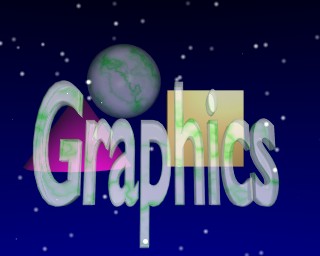
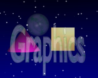
In these images, the text and the sphere in the background share the same material. I've added some mist to the "World" to give a greater appearance of depth. I used two lamps to light the scene. "Hard" was set to 150, "SpTr" to 0.5, and "Alpha" to 0.5 in one image and 0.2 in the other. Of course, I also turned on "ZTransp". When I rendered the image, I turned on the OSA (OverSAmpling) toggle in the Render Buttons, and set the level of oversampling to 16 in order to get a high-quality antialiased image.
As one of your assignments for the lab, see what you can do with transparency.
Blender has a special type of material called "Halo". Halo materials can only be applied to mesh objects and to particle systems. They are particularly useful in particle system animations, as you will see below. But you can get an idea of how they work by applying a halo to a standard mesh object. An IcoSphere is a good choice for this. Add one to your scene. Add a new material to your IcoSphere. Make it a Halo material by turning on the "Halo" toggle right in the center of the Material Buttons. A lot of the other buttons will change. For example, the three color patches are now called "Ring", "Line", and "Halo". You can use these to set three different colors associated with the Halo material. Just below the color patches, there is a "Halo Size" button.
Halos emit their own light, so they don't have to be lit by lamps to be visible in a rendered image. Hit F12 (with the mouse pointing at the 3D window) to render an image of the IcoSphere with the default Halo material. There is a little halo of light at each vertex of the IcoSphere. Change the Halo color to something more interesting than gray, and increase the Halo size to 1.00, and render the image again. Not bad, huh?Just above the "Halo" toggle button, you will find additional toggles labeled "Rings", "Lines", and "Star". The "Rings" and "Lines" toggles add additional shapes to the halo. You can set the colors of the rings and lines, and you will find buttons for controlling the numbers of rings and lines. The "Star" toggle just reshapes the basic halo into a star shape. You can specify the number of points of the star.
Parenting: Hierarchical Models in Blender
Hierarchical structure plays an important part in computer modeling, since it lets you build a model from component pieces and then treat that model as a single object. In blender, you can set one object to be the parent of one or more other objects. After you do this, the child objects are carried along when you transform the parent. Children can also have their own transformations (and animation).
To create a parent relationship, select both the child object(s) and the parent object simultaneously. (Use SHIFT-right-click to select multiple objects.) The last item selected is the "active" object. This is the object that will become the parent. Hit CTRL-P. You will be asked to confirm that you want to make a parent. After you confirm this, the children will be connected to the parent by dotted lines. Try dragging or resizing the parent to see that the transformation applies to the children. Try dragging or resizing a child to see that the child can have its own transformation. If you want to remove a parent relationship, select the child and hit ALT-P.
I mention parenting here partly because it is used in several techniques which I will cover later in the lab.
Rendering and Saving Animations
The rest of this lab is about animation techniques. First, however, some general discussion about animations.
You can preview your blender animations in the regular 3D window. The left and right arrow keys can be used to move from one frame to the next. The up and down arrow keys move you in ten-frame increments. SHIFT-left-arrow and SHIFT-right-arrow move you to the beginning and end of the animation. (The ending frame of the animation is set in the Display Buttons, in a numerical button named "End:".) You can also enter a frame number directly in the frame number button in the header of the 3D window. Hit ALT-A to start animation playback mode in a 3D window, and hit ESC to stop the animation. If you have several 3D windows, SHIFT-ALT-A will animate all of them.
When you are ready to render a final version of your animation and save it to disk, you have to start thinking about quality and disk space. Blender can save an animation as a set of files, with each image in a separate file. It can also save all the frames in a single file in AVI format. It can make two types of AVI files: AVI Raw and AVI JPG. AVI Raw files are VERY large. The last one I made was 35 megabytes. It's not really possible to use Raw AVI files over a network. So, you wouldn't want to store them in your "M" drive, even if you had the space. However, you can save them onto the C drive of your local computer and work with them there. AVI JPG files can be much smaller because they are compressed. However, a typical Windows setup can't deal with them. (In Linux, you can play both AVI Raw and AVI JPG files using the "xanim" command. You can also play all blender animations from within blender.)
If you want to post a blender animation on your Web page, I suggest that you transform it to a different format. MPEG is a reasonable choice because it is a universal standard. Here are links to two MPEG versions of one of my blender animations. The first version is OK for on-campus viewing. The second, smaller version would be better for people off campus who have to deal with slow internet connections. Clicking on either link will probably open Windows Media Player to play the animation. You might get a dialog box asking you whether you want to open the file or save it to disk. Look at them both:
Bounce Animation MPEG, 320x256 (850K)
Bounce Animation MPEG, 160x128 (90K)
I've found a free program for Windows that can transform AVI Raw files into MPEG files. It seems to work OK for some animations, not for others. Your mileage may vary. It's called avi2mpg1 and there's a copy in the cpsc324 directory on the "N" drive. This is a command line program, so you will have to open a command window to use it. I've included a copy of the program command.com in the same directory. You can double-click this program to open a command window. Here is a list of steps that you can use to make your animations:
- In the Display Buttons, select "AVI raw" as the output type. (Or "AVI jpg" if you have a use for it.) You can leave the "Frames/sec" set to 25, but for a Web animation, you might want to reduce it to 10 or 15. (The avi2mpg1 program can only handle certain frame rates.)
- Set the full path name to be used for the output file. This has to be entered in the text input button in the upper left corner of the Display Buttons window. Click this button and type a new name, or click the small rectangular button to the left of the name to select the file using a file window. You can use something like "C:\animname.avi" or, if you want to put the file in a directory, "C:\windows\temp\animname.avi". Be careful with the directory. If it doesn't exist, blender will simply fail to save the animation, without giving any error message.
- Set the size of the image, using the "SizeX" and "SizeY" buttons. The default, 320 by 256, is OK if you want a big file size for on-campus use. Cut these in half to 160 by 128 for a smaller size.
- I suggest the you turn on the "OSA" toggle for antialiasing. You might want to try turning on the "MBLUR" toggle for a motion blur effect. If you are using spotlights and want to see shadows, turn on the "Shadows" toggle.
- Set the numbers in the "Sta:" and "End:" buttons to the starting and ending frame for your animation. This determines the length of the animation.
- Hit the "ANIM" button to render the animation. You can abort the process at any time by pressing the ESC key. After the animation is complete, you can hit the "PLAY" button to see the final product. You might want to save your blender file at this time so you don't lose all your settings. Note that you can play the animation later from within blender without rendering it again, as long as you have the correct full path name for the avi file filled in.
- Now, convert the avi file to mpg. Open a command window. Enter "C:" as a command to change
to the C drive and cd to "\" or to whatever directory you stored the avi file in.
To run the conversion program, use a command something like:
N:\cpsc324\avi2mpg1 -n -s 300 animname.avi
The "-n" is required for an avi file that does not contain sound. The "-s 300 specifies the desired bit rate for the movie. The mpg file will be compressed to whatever degree is necessary to achieve this bit rate. If the bit rate is too low, it can look very bad. The 300 seemed to work for my large file animation. For the small file animation, I used "-s 120". However, I think that the results will also depend on the complexity of the scene. You might have to experiment to get good results. The output file from the above command will be named "animname.m1v". Supposedly, m1v is the correct extension for an mpeg file without sound. However, you can rename the file to "animname.mpg", using the more common .mpg extension. - To post your animation on your Web page, you should FTP the file over to your account on math, or mount your math account as a Windows network drive and copy the file. As usual, you will probably have to change the permissions on the file. A link to the file will look like any other link on a Web page. See the source code for this page for an example.
Note that you can render any individual frame as a still image. Just make sure the frame number is set in the frame number button in the window header, render the image as usual, and save it using the Save Image command (F3).
Keyframe Animation and IPO Curves
You saw an example of keyframe animation in the first lab, and I demonstrated it in class on Thursday. The idea is that you can "insert a key" by hitting the "I" key and selecting the items for which you want to insert a key. This inserts one or more key values for the current frame. You can change the frame number, modify the scene, and then insert another key of the same type. Do this for as may frames as you like. When you play back the frames in an animation, values will be interpolated between the key values that you specified.
In the 3D window, you can insert key values for location, rotation, and/or size of the selected object. Note that in addition to regular objects, you can animate the camera in this way, and you can also animate lamps. You can insert keys for material values by pressing "I" in the Material Buttons window. You can also animate World properties by pressing "I" in the World Buttons window and for lamp properties by pressing "I" in the Lamp Buttons window.
Any value that has been "keyed" in this way can be visualized as a curve that plots the value as a function of frame numbers. These curves are called IPO curves (InterPOlation curves). The IPO curves for the selected object are shown and can be manipulated in an IPO window. You could split the 3D window and change one of the windows to an IPO window. This has already been done for you in one of blender's standard screens: Select the first screen from the screen menu in the header at the top of the screen.
An IPO window shows the IPO curves only for the currently selected object. Furthermore, it will only show one type of curve at at time: Object IPOs for location/rotation/size; Material IPOs for color/transparency; etc. There are small buttons in the IPO window header that you use to select the type of IPO curve that is shown. Each curve has a name. The names are shown along the right edge of the window. When you left-click a name, the corresponding curve becomes visible and other curves are hidden. SHIFT-left-click to show multiple curves. (Initially, all the curves are visible anyway.) Next to each name is a colored rectangle. This shows the color of the curve. You can select a curve by left-clicking the colored rectangle or by right-clicking the curve itself. Use the SHIFT key to select multiple curves.
The usual editing features work in the IPO window. You can drag or scale a selected curve using the "G" key or "S" key as usual. Hit TAB to put the selected curve in edit mode. You will see the curve is actually a Bezier curve with control points and handles that you can manipulate in the usual way. Remember that while you are in edit mode, you can only work with the selected curve. The Home key can be used to scale all the curves to just fit in the window.
Towards the right end of the IPO window header, you will find four little buttons that determine what happens to the IPO curves outside the range of frames for which you specified key values. The first setting, which is the default, is that the value stays constant. The button for this option shows a horizontal arrow. The next button causes the curve to be extended in the direction that it is heading at its endpoint. The third option is to repeat the same curve over and over. The fourth option repeats the same shape over and over, but the shape will be moved vertically or horizontally to make the endpoints match up. To change the setting, select the curve or curves that you want to modify, and hit the appropriate button.
Tracking
You can set one object to "track" another, that is, to rotate so that it always faces the other object, even as that object is dragged or animated. You can do this with any object, but it most useful to do it with cameras. By using tracking, you can set the camera so that a given object is always kept in the center of the view.
To set up tracking, select the camera (or other object that is to do the tracking) by right-clicking on it. Then extend the selection to the object that is to be tracked by SHIFT-right-clicking on it. The order in which you do this is important. Now, hit CTRL-T. You'll get a dialog box that asks you to confirm that you want to set up tracking. Once you do this, you should see that the camera rotates when you drag the tracked object. However, the camera is still not pointing directly at the object. This is because the camera still has its own rotation, which is applied in addition to the tracking rotation. You have to clear this rotation. Select the camera again, and hit ALT-R. You will have to confirm that you want to clear the camera's rotation. Now, the camera should point at the tracked object. Hit the keypad-0 key to see the view from the camera.
Sometimes, you don't want to track an actual object. You just want to track some particular point in space. For purposes like this, blender provides empty objects. If you add an "empty" to a scene, it is displayed in the 3D window as a set of xyz-axes. However, it doesn't show up in the rendering. You can animate an empty just like any other object. You can set the camera to track an empty object. You can even use an empty object as the parent of other objects.
The sample animation from earlier in the page uses tracking. The camera tracks an empty object that sits on the top of the pedestal. In this case, the camera itself is animated using path animation, which is discussed below. The blender source file for this example is called bounce.blend.
Path Animation
It's possible to make an object move along a curve. A curve used in this way is called a "path" in blender, and the technique is called path animation. To make a Bezier or NURBS curve into a path, select the curve, go to the Animation Buttons, and turn on the "CurvePath" option. Now, any object that is parented to the curve will move along the curve as you animate the scene.
As an example, add a Bezier circle to the scene. Scale it up to about five times its original size so you can see what's going on better. Go to the Animation Buttons and turn on the "CurvePath" option. Add a cube to the scene and parent it to the curve. (Rigth-click the cube, then SHIFT-right-click the curve, in that order, then hit CTRL-P and confirm that you want to make a parent.) Hit the arrow keys to change the frame number and you will see that the cube moves. However, it does not actually lie on the curve. You can force this behavior if you want. Erase the cube and add another (or simply remove the parent relationship by selecting the cube and hitting ALT-P). Now, parent the cube to the curve again, but this time use SHIFT-CTRL-P. You will be asked whether you want to "Make Parent Without Inverse". Confirm this, and the cube will jump to the curve. And it will follow the curve exactly during the animation.
Let's try this with the camera. Delete the cube. Parent the camera to the curve using SHIFT-CTRL-P, and the camera will follow the curve. This technique can be used to make "fly-through" animations. However, it's possible that you want the camera to point straight ahead along the curve. You just have to do two things: Select the curve, and turn on the "CurveFollow" option in the Animation Buttons. This makes the camera adjust its rotation to the direction of the curve. Then you also have to clear the camera's built in rotation: Select the camera, and hit ALT-R. You now have the right setup for a fly through. You could use the same technique to make an airplane fly along a path, for example. This technique is used in the sample file flythrough.blend. (I didn't include an MPEG of this scene because it looked terrible. I think the scene changes too fast for MPEG to be able to handle it. MPEG depends on similarities between consecutive frames to do its compression.)
The length of the path -- the number of frames that it takes for an object to move along the path -- is set using the "PathLen:" button next to the "CurvePath" toggle. However, the motion of the object along the path can also be controlled by an IPO curve called a "speed IPO". If the curve has a speed IPO, then the PathLen button is ignored. Blender has a type of curve object called a "Path" which is set up with CurvePath already turned on and with a speed IPO. (It also has the "3D" toggle turned on in the Edit buttons, so you can shape it in three dimensions instead of just in a plane.) To see the speed IPO in the IPO window, you have to select the curve and set the IPO window to show Animation IPO's (by clicking on the squiggly arrow icon in the header). You can edit this IPO curve just like any other. For example, you can make it cyclic. Blender's Path object is a NURBS curve, which means that the curve doesn't necessarily pass through its control points. It's supposed to give very fluid motion. I used a Path object in my fly-through animation, but I deleted its speed IPO so that I could set the path length to 300 in the "PathLen" button.
Particle Systems
Particle systems have become very popular for modeling natural phenomena such as flames, smoke, flocks of birds, fireworks, and confetti. In blender, particles are emitted by a mesh object, such as a plane, a mesh circle, or an icosphere. The particles act like extra vertices that are spawned off the mesh, drift away, and disappear after a certain number of frames. Usually, the mesh is given a Halo-type material, so that each particle appears as a Halo. As discussed below, particles can also be used with a technique called "Dupliverts". When a mesh is used as a particle emitter, the mesh itself is not rendered. However, note that you can animate the mesh so that the source of particles moves, rotates, and/or changes size. I will discuss some of the basics of particle systems here. Using them for realistic modeling is not trivial, and it is not a skill that I have learned just yet.
When a particle is created, it is given some initial velocity, which can include a certain amount of randomness. It can be subject to forces in the x, y, and z directions. It has a lifetime of a certain number of frames. At the end of that lifetime, it's possible for it to generate additional particles.
To turn a mesh object into a particle system, select the object and go to the Animation Buttons. Click the "New Effect" button. In the pop-up menu that appears to the right of this button, change "Build" to "Particles". A large number of particle system controls will appear. Working with particle systems consists mainly of using these controls (and setting the Material properties of the mesh). To give you an idea what some of these controls are for, step through the following tutorial, and then do some experimenting on your own:
- Start with a new scene. Add a mesh plane to the scene (if its not already there). Leave edit mode, but leave the plane selected. Go the Animation Buttons and add a Particle effect to the mesh.
- Switch to a side view (hit Keypad-3) so you will be able to see the particles better.
- By default, particles don't move. Click once on the right end of the "Norm:" button to change its value to 0.100. This button specifies how much initial velocity the particles get in the direction of the normal vector to the mesh object at the vertex where the particle is created. (The setting of the "Ob:" button is useful if the emitting object is animated: It adds some fraction of the emitting object's velocity to the particles. The "Damp:" button can be used to add "friction" that will cause the particles to slow down as they move.)
- Use the arrow keys to see what happens when the frame number is varied from 1 to 150. A stream of particles is created and moves upward. A total of 1000 particles are created, starting in frame 1 and ending in frame 100, and each particle has a lifetime of 50 frames. These four values are controlled by the "Tot:", "Sta:", "End:", and "Life:" buttons.
- Increase the value on the "Rand:" button from 0.000 to about 0.100. This adds some extra, random initial velocity to the particles. Go through frames 0 to 150 again. Now you see a cloud of particles instead of lines of particles.
- At the bottom left of the particle system controls are three "Force" buttons labeled "X:", "Y:", and "Z:". These apply forces to the particles in the x, y, and z directions, Increase "Y:" to about 0.200, and the particles are blown to the right, in the direction of the positive y-axis. Set "Z" to about negative 0.2 and the particles will accelerate toward the ground, in the negative direction of the Z-axis, as if under the influence of gravity.
- Render the scene for one of the frames where some particles are visible. The particles are assigned a dull gray halo material by default.
- Change to a nicer Halo material. Make sure the emitter is still selected, go the Material buttons, and add a new material. Turn on the "Halo" toggle. Adjust the colors. Add some rings or lines. Render the scene again. (Note: You can, of course, animate Halo materials. There is one oddity: The material animation that you specify for frames 1 through 100 is applied to each particle individually over the course of its lifetime. The 100 frames are scaled to the actual lifetime of the particle.)
It's possible to have multiple generations of particles, where a particle generates new particles at the end of its lifetime. The "Mult:" button specifies what fraction of particles generates new particles, and the "Child:" button specifies how many new particles are generated from each particle that reproduces. It is possible to assign different materials to different generations of particles, but I will leave you to look up the details if you want. You should note that the total number of particles, as specified in the "Tot:" button, seems to refer to the total number including the child particles.
If you have an emitter with a lot of vertices, you will see that particles are emitted from the vertices in a certain sequence. You might want to randomize this sequence. To do so, select the emitter and go into edit mode. Select all the vertices by hitting the "A" key. Go the Edit Buttons and hit the "Hash" button. This will randomize the order of the vertices. (For some applications, you might want to sort the vertices instead. That's what the "XSort" button is for.)
Dupliverts
One of the options that you can turn on in the Animation Buttons is "Dupliverts". Actually, it is not an animation, but it is often used with particle system animations. This option can be used to place a "virtual" copy of an object at every vertex of a mesh or at every particle in the particle system associated with a mesh. Here is how you use this option:
- First, the object that is to be duplicated must be parented to the mesh. Right-click the object, then SHIFT-right-click the mesh. Hit CTRL-P and confirm that you want to create the parent relationship.
- Now, select the mesh only, by right-clicking it. Go to the animation buttons and turn on the "DupliVerts" option. You should now see multiple copies of the object. (If there is a particle system associated with the mesh, make sure you are in a part of the animation where some particles are visible!)
- If you are using a particle system, you probably want to turn on the "Vect" option in the particle system settings. This will make the duplicated object rotate along with the particles.
Although the original object remains visible in the 3D window, it will not be visible in the final rendered scene.
Here is a particle system animation that uses this technique:
Confetti Particle System MPEG, 160x128 (85K)
The duplicated object is a small square. Unfortunately, all the duplicated objects created by "DupliVerts" will be identical to the original, so I had to use three separate particle systems to get three different colors on the squares. (Remember that you can make duplicates with ALT-D.)
As another example, here is a still image that uses DupliVerts twice. It's used on a subdivided plane to make a wall of translucent red cubes. And it's used on a mesh circle with 12 vertices to make a circle of green cones.
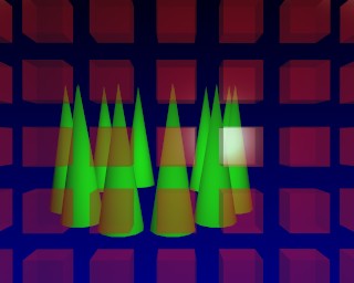
You will find the blender source files for the two DupliVerts examples under the names confetti.blend and dupliverts.blend.