Today's lab is mostly about textures, with a little extra information thrown in about lighting and spotlights. For your lab report, you should produce one or more images that use a variety of textures and texture effects. You can use the sample blender file, objects.blend, as a starting point if you like. In addition to this, make a scene from scratch that uses a spotlight with visible shadows. Your scene should use either an environment map or a spotlight with either a halo effect or a texture or both.
The "cpsc324" folder on the "N" drive contains the sample file objects.blend. It also contains a directory named "textures" which holds some image textures that you can use in the lab. You will find copies of the same stuff on the math server in the directory /home/cs324/blender.
Textures in Blender
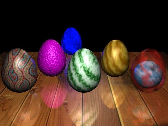
Blender uses the term "texture" to refer to a variety of effects that influence the appearance of a surface, including 2D image textures, 3D procedural textures, bump maps, and environment maps. Here is a sample image that uses all of these effects. The source file for this image is eggs.blend.
I will tell you how I made each of the eggs, but first, let's look at some of blender's control buttons for texturing. Since textures are so complicated, there are a lot of them, and they are divided between the Material Buttons and the Texture Buttons. In general, the Texture Buttons control the properties of the texture itself, while the Material Buttons control how the texture is applied to the material. In blender, a material can have up to eight textures, which are applied to the material one after the other. Of course, using more than one texture only makes sense if you use the texture to blend with the material in some way rather than to replace it.
To add a texture to an object, that object must first have a material -- even if you intend to completely cover the material color with a texture. (In fact, an image texture usually replaces only the diffuse color of the material, leaving the specular color intact.) After adding the material to the object, go the Texture Buttons. You'll see a list of texture types along the top of Texture Buttons Window. Select one of these by clicking on it. A new set of buttons for controlling that type of texture will appear. There is a square area at the left end of the buttons window that shows a preview of the texture. Just to the right of this is a column of buttons. Each of these buttons represents one of eight possible textures to be applied to the material. When you add the first texture, the name of the texture goes in the first button. To add a second texture, click the second button and then click one of the texture types to add the texture. If you want to change the settings for one of several textures, just click the corresponding button to see its settings. Remember that textures will be applied to the material in the order that they are listed.
To control how a texture is applied to a material, you have to go back to the Material Buttons. There are a lot of options. The whole right side of the Material Buttons Window is devoted to this. Let's take a look at it:
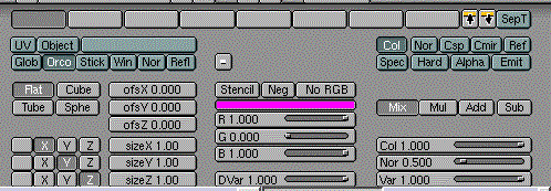
I don't understand all of these controls, but I will describe the ones that I do understand.
Along the top are eight buttons representing the eight possible textures. Select the texture that you want to work on here. The preview at the left of the Material Buttons Window ordinarily shows the effect of applying all the textures to the material. If you click the "SepT" toggle on, the preview will show only the selected texture. This can make it easier to adjust the controls.
The group of buttons that starts "UV", "Object",... controls how texture coordinates are computed. The default selection, "Orco", uses the "original coordinates" from the object that is being textured. That is, it will base the texture coordinates on the (x,y,z) coordinates of the object in its own coordinate system. This is the most common option. The other aren't so useful. For example, the "Glob" option uses global (x,y,z) coordinates. That is, the texture is fixed in space and as the object moves it will slide through the fixed texture. Later, we will see that the "Refl" option is used for environment maps.
The four buttons labeled "Flat", "Cube", "Tube", and "Sphe" determine how a 2D image texture is projected onto an object. That is, how are the three texture coordinates transformed into (s,t) coordinates on the image.
The "ofsX", "ofsY", and "ofsZ" buttons are used to set a texture transformation. These buttons apply offsets to the three texture coordinates. Similarly, "sizeX", "sizeY", and "sizeZ" apply scaling to the texture coordinates. Remember that scaling the texture by a factor of K will make the texture K times smaller on the object. (You can, by the way, animate the texture transformation values to give textures that move or grow.)
The color sliders in the middle set the color that is used for blending by intensity textures such as marble an clouds. The intensity of the texture at a point determines how much of this color is blended into the original color of the material. The "Neg" button in the intensity texture reverses black/white in the intensity texture.
In the next column, the buttons labeled "Col", "Nor", etc, determine which aspect of the material is affected by the texture. The default is "Col", which means that the diffuse color of the material is affected. "Nor" means that normal vectors are affected, so you get the effect of a bump map. I think "Csp" is the specular color. "Cmir" is used for environment maps. "Ref", "Spec", "Hard", "Alpha", and "Emit" affect the corresponding values of the material. (These values are the same ones that are controlled by the sliders at the bottom left of the Material Buttons.) Some of these buttons are three-position toggles. The toggle can be on, off, or negative. Also, note that you can choose to apply the texture to several aspects of the material.
Once you know which aspect of the material is to be affected by the texture, you still have to say how it will be affected. The next set of four buttons determine whether the texture value is mixed, Multiplied, Added, or Subtracted. (Not all of these make sense in all contexts.) Finally, there are three sliders which determine the degree to which the material is affected. If the texture is affecting the color, the "Col" slider says how much of the texture color is mixed into the material color. If this slider is 1.000 (the default), then the texture color completely replaces the material color. For smaller values, the texture color is blended with the material color. The "Nor" slider controls the extend to which the texture affects the normal vector. This slider has an effect only if the texture is set to affect the normal vector. The "Var" slider determines the extent to which the texture affects a value such as "Alpha" or "Emit", and it has an effect only when the texture is set to affect such a value.
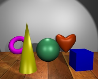 For this lab, you have to apply a variety of textures to objects. You can, if you like, use the
objects in the sample file, objects.blend. Open this file now. It contains a scene
that renders as the image shown to the right. The wooden floor is really an image texture
applied to a mesh plane, with all the default settings. As a first exercise in image textures,
you should add an image texture to the plane at the back of the scene. First, select this
plane and add a material. Then go to the Texture Buttons, add a new texture, and select
"Image" as the type of texture. You'll see a variety of controls for image textures. The most important
of these are the "Load Image" button and the text field next to it that shows the name of the image
file. Currently, the file name is empty. Click the "Load Image" button. You will get a file-open
window where you can select the image. Navigate to the directory N:\cpsc324\textures. You will
see a preview of all the images in the directory. Select "stone.jpg" by clicking on it with
middle mouse button.
For this lab, you have to apply a variety of textures to objects. You can, if you like, use the
objects in the sample file, objects.blend. Open this file now. It contains a scene
that renders as the image shown to the right. The wooden floor is really an image texture
applied to a mesh plane, with all the default settings. As a first exercise in image textures,
you should add an image texture to the plane at the back of the scene. First, select this
plane and add a material. Then go to the Texture Buttons, add a new texture, and select
"Image" as the type of texture. You'll see a variety of controls for image textures. The most important
of these are the "Load Image" button and the text field next to it that shows the name of the image
file. Currently, the file name is empty. Click the "Load Image" button. You will get a file-open
window where you can select the image. Navigate to the directory N:\cpsc324\textures. You will
see a preview of all the images in the directory. Select "stone.jpg" by clicking on it with
middle mouse button.
If you render the image, you'll see the stone texture on the plane. However, it looks too "stretched out" to me. To fix this, apply a texture transform: Go the Materials button. Enter 3.000 as the value of "sizeX" and 2.00 as the value of "sizeY". This will make the texture repeat 3 times in the horizontal direction on the plane and 2 times in the vertical direction. The rendered image should look better now. If you would like to "tint" the stone texture by blending in some color, set a color for the material and set the "Col" slider in the bottom right of the Material Buttons to a value less than one. This will make the stone texture blend with the material color.
To help you to understand the variety of things that you can do with textures, I will explain how I textured each of the Easter eggs in the image at the top of this page:
- The paisley egg has a simple image texture, paisley.rgb, applied. The texture projection was set to "Cube". Note that the "Sphere" texture projection rarely gives good results, except with textures that are specifically designed to be projected onto a sphere.
- The purple egg has a bump map applied to a purple material. The bump map is actually a "Stucci" texture. To get a bump map, I turned off the "Col" toggle and turned on the "Nor" toggle in the group of buttons at the upper right of the material buttons. I set "sizeX", "sizeY", and "sizeZ" to 3 to get smaller bumps. And I set the "Nor" slider at the bottom right to 3.252 to get deeper bumps. (You can apply image textures as bump maps! Try applying the image bricks2.rgb to the "Nor" channel of a material, or try applying it to both "Col" and "Nor".)
- The marble egg uses a very light green material color and two marble textures. The first texture is a medium green with fairly wide stripes. It has the "Sharp" option set in the Texture Buttons. The second texture is a very dark green, and it shows up as dark, narrow lines in the middle of the medium green stripes.. For this one, I turned on the "Sharper" option in the Texture Buttons. I also turned on the "Neg" option above the texture color sliders in the Material Buttons. Without this option, I would have had very wide dark bands with narrow light-colored lines.
- The wooden egg has two textures. The first is a standard "Wood" texture which combines a brown texture color with a yellowish material color. However, I wanted to add some "grain" to the wood. For this I added a second texture, of type "Clouds". The texture color for the Clouds texture is a dark brown. I set "sizeX" for this texture to 9.40 so that the clouds would be collapsed into thin vertical stripes. I set the "Col" slider, at the bottom right, to 0.608 to reduce the effect of the Clouds texture on the material.
- On the far right is a partly transparent egg with a sphere inside it. The sphere has an image texture, sky.rgb. The egg has a red material color and a Marble texture. However, I set the texture to affect the "Alpha" of the material, rather than the "Col". I also had to change the mode of the texture from "Mix" to "Mul". That is, the alpha of the material is multiplied by the texture intensity. Where the texture is white, the material becomes transparent. Where the texture is black, the material is unaffected. I set the "Var" slider to 0.818 to reduce the effect of the texture, so that no part of the egg becomes completely transparent. To make the egg actually be see-through, I also had to turn on the "ZTransp" toggle in the middle of the Material buttons.
- In the background is a blue egg with a marble texture. In this case, I set the texture to affect the "Emit" of the material rather than the "Col", so it looks like there are some glowing stripes on the egg. Since emissive color does not actually give off light that affects other objects, I also added a blue light inside the egg. You can see the glow from this light on some of the other eggs.
Lighting
Setting up nice lighting for a scene is an important part of modeling that we haven't really covered yet. Lighting a 3D graphics scene is similar to lighting a physical movie set or stage, so some of the techniques that are used for lighting on the stage are relevant here. There are some standard techniques for placing lights. Here is how this is described in The Blender Book, by Carsten Wartmann:
Traditional films or TV productions frequently use a lighting scheme called a three-point system. This scheme typically has one key light that simulates natural light in the scene... In general, this light source is situated 30 to 45 degrees away from the axis between the camera and the filmed object and is also raised 30 to 45 degrees from the axis.
Fill light is commonly used to soften the shadows created by the primary light source. Fill light is less bright than the primary light, and is diffused to avoid throwing hard shadows. If the fill light is too strong, the scene will appear flat with minimal contrast. The fill light is commonly placed at the same level as the camera...
The back light... is placed outside the camera's view, where it illuminates from behind and over the filmed object to emphasize the object's contours and to set it off from the background. The back light must not shine directly into the camera objective.
I tried to do something like this in the scene in objects.blend. Keeping in mind the fact that in blender only spot lights can cast shadows, I used a spotlight as the key light. The other two lights are regular lamps (that is, point light sources).
When you use a spotlight in blender, remember to turn on the "Shadows" toggle in the Display Buttons. Otherwise, the shadows won't be rendered. When you have a spotlight in a blender 3D window, you see a line running down the center of the spotlight's cone. This line shows the range of distances from the light in which shadows will be cast. You can get sharper shadows by shortening this distance, since a shorter distance makes better use of the memory that blender uses for calculating shadows. The extent of this line is controlled by the "ClipSta" and "ClipEnd" buttons in the Lamp Buttons.
You can turn on a "Halo" effect for a spotlight. This is supposed to simulate what happens when light rays are made visible by dust, smoke, or mist in the air. The intensity of the effect is determined by the "HaloInt" button. You can also add a texture to a light. The right side of the Lamp Buttons is used to control how the texture is applied to the light. It is similar to the texture control in the Material Buttons. Try it, for example, with a "stainedGlass" image texture.
I've had a lot of trouble aiming a spotlight. An easy way to do this is to make it track an object. You can use an object in the scene or an empty object introduced just for this purpose. This can make it particularly easy to keep the spotlight pointed at a moving object during an animation. (Recall how to set up tracking: Select the spotlight by right-clicking it. Add the object that it will track to the selection by shift-right-clicking it. Hit CTRL-T and confirm that you want to set up tracking. Select the spotlight again and hit ALT-R. Confirm that you want to clear the light's rotation. It should now point directly at the object that it is tracking.)
Environment Maps
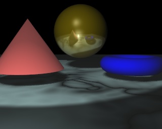 Environment maps are used to simulate reflection of the scene in a shiny object. Blender does
environment mapping by making six images of the scene -- one view in each direction from the
position of a specified reference object. These scenes are then used as a texture on the
reflective object. In the image at the right, an environment map is applied to the sphere.
In the textured eggs image at the top of this page, an environment map is applied to the
plane on which the eggs are standing.
Environment maps are computed automatically in blender, once the parameters are set up.
If you are doing an animation, you can even have blender compute a new environment map
for each scene.
Environment maps are used to simulate reflection of the scene in a shiny object. Blender does
environment mapping by making six images of the scene -- one view in each direction from the
position of a specified reference object. These scenes are then used as a texture on the
reflective object. In the image at the right, an environment map is applied to the sphere.
In the textured eggs image at the top of this page, an environment map is applied to the
plane on which the eggs are standing.
Environment maps are computed automatically in blender, once the parameters are set up.
If you are doing an animation, you can even have blender compute a new environment map
for each scene.
I have only been able to get good environment maps on spheres and planes. Here are the steps for adding an environment map to a sphere:
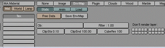
- Select the sphere, make sure it has a material, go to the Texture Buttons, add a new texture to the sphere, and set the type of the texture to "EnvMap". You will see the Environment Map controls, which are shown below.
- In the button labeled "Ob:", enter the name of the sphere. (You can get this name from the header in the Edit Buttons, as usual.)
- Move the sphere to a different layer. (Select the sphere, hit the "M" key, and select the layer you want to move it to.) In the environment map controls, under "Don't render layer", click on the layer that now contains the sphere. This is so that the sphere itself won't appear in the environment map. In the 3D window header, turn on the layer that contains the sphere if it isn't already on (by shift-clicking on the corresponding little button).
- In the environment map controls, you will probably want to increase the "CubeRes" to 250 or more. This determines the size of the images created for the environment map. If it's too small, the reflection will be blurry.
- You have to go back to the Material Buttons and make some changes. Change the texture coordinates from the default "Orco" to "Refl". For the texture mode, turn off the default "Col" and turn on "Cmir". If you render now, the sphere should look like a perfectly reflective mirror.
- You can add a color tint to the reflection by setting the "Cmir" color at the left end of the Material Buttons. To blend the environment map into the sphere's material, rather than replacing it, you can turn down the value on the "Col" slider at the bottom right of the Material Buttons.
- If you edit the scene, a new environment map will not be computed automatically. To force a new computation, go to the Texture Buttons and click the "Free Data" button in the environment map controls. To automatically recompute an environment map for each frame of an animation, click the "Anim" button.
The procedure for environment mapping a plane is the same, except for step two. You have to be really careful about the reference object used for a planar reflection. The reference object must mirror the portion of the camera, reflected through the plane. (Think of it like this: what the camera sees reflected in the plane should be the same as what the reference object sees directly.) To set up the reference object for reflection in a plane, do the following:
- Choose a view in which the plane is perpendicular to the screen, so you see it edge-on.
- Select the camera by right-clicking on it. Hit Shift-S (the "snap" command), and choose to snap "Curs->Sel" to snap the cursor to the selection. The 3D cursor will jump to the camera.
- Add an empty object to the scene. It appears at the camera position.
 Select the plane by right-clicking on it. Hit Shift-S and choose "Curs->Sel". The cursor jumps
to the plane.
Select the plane by right-clicking on it. Hit Shift-S and choose "Curs->Sel". The cursor jumps
to the plane.
- Set the reference point for scaling to be the cursor, rather than the center of the object. To do this click the small button in the 3D window header shown at the right.
- Select the empty object by right-clicking it. Without touching the mouse, hit the "S" key to start scaling, the "Y" key to reflect the empty through the plane, and the "Return" key to finish the scaling. The empty object should now be exactly on the opposite side of the plane from the camera.
- Enter the name of the empty object in the "Ob:" button in the environment map controls.
Then, continue with step (3) above. (You still have to move the plane to a different layer and set the environment map to not render that layer.)
Running blender in the Background
If you are writing a big blender animation that will take a long time to render, you might want to run it in the background on one of the cslab computers. Please do not do this on math.hws.edu, since that computer is busy being a server. Even on the cslab machines, please do the rendering in "nice" mode so it will not interfere too much with foreground tasks.
An easy way to run something in background while you are not logged in is to use the "at" command. This command lets you enter a list of commands to be executed at a specified time. To run some commands at 3:00 AM, just say: at 3:00 AM and then type the commands in the same way you would enter them to run them directly. Hit CTRL-D to end the list of commands. If you want to start running the commands in, say, 2 minutes, you can say: at now + 2 minutes
Your account is set up with a CPU time limit of ten minutes, so that a process will be killed after it uses 10 minutes of processing time. However, it is possible to remove this limit. The command to do this is ulimit -t unlimited.
To render a blender animation in the background, with no graphical interface, set everything up in your blender file to the point where you are ready to click the ANIM button to render the animation. Make sure the file name, number of frames, and output format are correct! Save the blender file. Let's say it's called "anim.blend". Quit blender. Then enter the "at" command with the time when you want to run the job. When "at" prompts you for commands, enter:
         ulimit -t unlimited
         nice blender -b anim.blend -a
         >CTRL-D<
Replace "anim.blend" with your actual file name. Later, you can use the "top" command to check if the job is running.