In this final lab of the term, you will take a short look at two advanced rendering techniques: radiosity and ray tracing. The point here is not to master these techniques but to become more acquainted with them and to see what they can do. You should try to generate one radiosity image and one ray-traced image, as described below, and put the two images on your web site before the end of the lab. If you don't manage to finish this during this lab, you should at least have the images on your web page before class on Thursday. If you find yourself with extra time today, you can use it to work on your programming assignment, Web portfolio, or final project.
Radiosity in Blender
Blender can do radiosity renderings, although the radiosity feature is not completely integrated with the rest of blender's features. And the interface is (surprise!) a little odd. Radiosity in blender works only with mesh objects, and it does not deal with textures at all. The only thing that matters is the diffuse and emissive colors of meshes in the scene. Any object that has a non-zero emission acts as a light source. The radiosity calculation will spread this light around the rest of the scene. The calculation uses the "shooting" method we talked about in class: The patch with the most unshot energy shoots its energy into the environment. This is repeated over and over until the total amount of unshot energy in the scene is below some specified limit -- or until you stop the process by pressing ESC. A nice feature of blender is that it shows you the process, so you get to see how the lighting changes as the process is iterated.
You will find several blender files set up for radiosity rendering in the directory N:\\fsrv\cpsc324\radiosity. These files came with the book The Blender Book, by Carsten Wartmann. Open the file conference_room04.blend. You will see several views of a conference room. Here is how to do the radiosity calculation for this room, or for any other scene:
- Point the mouse at one of the 3D windows, and press the A key once or twice to select all the objects in the scene. Only selected mesh objects will be part of the radiosity calculation. Most of the blender interface shuts down until you finish the radiosity calculation by clicking the "Free Radio Data" button.
- Go to the radiosity buttons, indicated in the Buttons Window Header by a little radiation symbol. We will ignore most of these buttons, and will use all the default settings.
- Click the "Collect Meshes" button. This collects the data needed for the radiosity calculation. The 3D windows will change in appearance
- Click the "Go" button and watch the window in the upper right. After a few seconds of preliminary calculation, the whole scene will go dark except for the objects that emit light. This is the initial setup for the radiosity calculation. The computer will then start shooting energy from patches, and you will see how the shot energy lights the scene. The patches are outlined in green. This starts off pretty quickly, so watch carefully.
- The cursor shows the number of patches that have shot. The process will stop automatically, or you can stop it whenever you want by hitting the ESC key.
- To save the results of the calculation, click the "Replace Meshes" button. This replaces all your objects with one giant mesh that contains the radiosity information. Then click "Free Radio Data" to return blender to normal operation. (If you click "Free Radio Data" without clicking "Replace Meshes", the results of the calculation are discarded. If you click "Add New Meshes", the data is applied to a newly created mesh which exists right on top of the original meshes. Ordinarily, you would immediately move the new mesh to another layer. This allows you to save the unmodified meshes as well as the new mesh.)
- You can now render the scene by pressing F12. If you want to save the image, you should first go to the Display Buttons and make sure that the image type is JPEG.
Note that blender expects that you will usually use the radiosity data as a basis for further modeling. For example, you might add lighting to the scene or apply textures. However, this involves some complications, so we won't go into that here.
Next you can try one of the files radiosity_box00.blend or radiosity_boxRGB_00.blend or both. These are simpler scenes, which are similar except that the RGB version has red, blue, and green colored lights. Do the radiosity computation on one or both of these files.
Your assignment to modify one of the sample files by adding and/or removing objects and lights. For a light, it's best to use objects with large faces, such as a cube or a plane. (The algorithm doesn't work well with small light-emitting faces because they don't contain a lot of energy individually. Another thing that I found out is that light is only emitted from the front faces of polygons. In particular, a mesh plane only emits light from one side. If that side is facing away from your objects, they won't be lit.)
You should run a radiosity computation on your modified scene, render an image, and add it to your web site.
Ray Tracing with POV-Ray
The free ray-tracing program, POV-Ray, is very full-featured and can be used to produce pretty fancy images. You might want to look through the large collection of images from the Internet Raytracing Competition at http://www.irtc.org/stills/index.html. (Note that each two-month competition has a winners page that includes a link to another "Viewing Page" with all the entries for that competition.) POV-Ray can also do animation and even has some support for radiosity. The input to POV-Ray consists of plain text files that contain scene descriptions written in POV-Ray's own scene description language. Although there are modeling programs that export POV-Ray scene description files for rendering in POV-Ray, it's possible to produce a POV-Ray file with a plain text editor. That's what you'll be doing in this lab.
You should work in your math account through X-Win32. Copy the file /home/cs324/starter.pov into your account. This file describes a scene that contains a variety of objects with a variety of colors and textures. You can render the scene with the command:
x-povray +Istarter
You will see the scene as it is being rendered. After the rendering is done, the rendered image will be in a file named starter.png. You can add a PNG file directly to your web pages, although there are still a few older browsers around that don't understand PNG images. Since PNG files are relatively large, you might want to convert the file to JPEG format. You could do this with Gimp. If you want a larger image, you can give the height and width on the command line. For example:
x-povray +Istarter +W640 +H480
And for a better image, at the expense of increased rendering time, you can turn on anti-aliasing by adding the "+A" option:
x-povray +Istarter +W640 +H480 +A
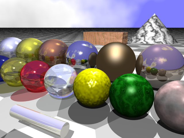
Open the file "starter.pov" in a text editor. It contains a sequence of object/light/camera specifications that set up the scene. You can use the same lights and camera, if you want, but they are pretty easy to figure out once you know something about the syntax. You should know that the z-axis in POV-Ray points into the screen rather than out of the screen as it does in blender. Also, points and vectors in POV-Ray are specified using angle brackets rather than parentheses, so <3,3,-6> represents the point 3 units over from the center, 3 units up, and 6 units in front of the screen. Let's take a look at the first object specification, which describes the ugly, bumpy yellow sphere in the center of the image:
   sphere {
     <0, 0, 0>, 1
     texture {
       pigment { color Yellow }
     }
     normal {
        bumps 0.3 scale 0.1
     }
     finish {
        phong 1
     }
   }
In this specification, the type of object (sphere) is followed by a block that specifies the properties of the object. The first item, <0,0,0>, is the center of the sphere. This is followed by the radius of the sphere, 1. Then, a texture, a normal map, and a finish are specified. In this case, the "texture" is simply a yellow "pigment", that is a solid yellow color. The "normal" specification is a bump map that makes the surface look bumpy. The "finish" adds a reflective hilite. Other items can also be added to an object specification, including interior properties for hollow objects and transformations. And the properties can get very complicated.
Fortunately, POV-Ray makes it possible to define macros, and a lot of standard macros are available in a number of standard include files. Two of these files, "colors.inc" and "textures.inc", are included at the top of starter.pov. Other standard include files can be found in the directory /usr/lib/povray31/include/. Some of the macros defined in these files are textures, some are pigments, etc. You can use a texture or pigment macro in a texture specification. For example, look at the second sphere in starter.pov:
   sphere {
      <2, 0, 0>, 1
      texture {
        Jade
      }
      finish {
         phong .5
         phong_size 20
      }
   }
Here, "Jade" is a macro that defines a pigment that is supposed to look like jade. I added a finish to this, since without the finish, it looks non-reflective and dull. For most of the objects in the scene, however, I simply used a pre-defined texture with no modification. For example, the most reflective of the spheres is defined as:
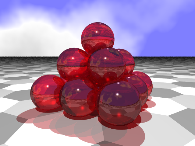
   sphere {
      <-3,.5,4>, 1.5
      texture {
         Polished_Chrome
      }
   }
Your assignment is to compose a simple scene that shows off some of the features of ray tracing. A classic scene, for example, shows a pyramid of glass or metal spheres. You can copy pieces of code out of starter.pov to create your scene. Put a rendered image of your scene on your web page.
David Eck, April 2001