CPSC 324, Spring 2004
Lab 10: Lighting and Materials
THIS LAB STARTS with a short tutorial introduction to lighting and materials in OpenGL, a topic that we have not yet covered in class. The second part of the lab offers more information about materials and textures in Blender.
Exercise 1: Following the instructions in the first part of the lab, make a "lit" model in OpenGL. Post a screenshot from the program on your Web site, and turn in a printout of your program.
Exercise 2: Get a copy of the file /home/cs324/blender/eggs_blank.blend. Apply materials and textures to the eggs and stage in this file, as described in the second part of the lab. Your work must use image textures, multiple textures on the same object, and applying textures in non-standard ways, such as to affect the alpha value of an object. Render your completed scene and add the image to your web site. Include a brief description of how you created the appearance of each object.
Lighting and Materials in OpenGL
 OpenGL has two completely separate systems for computing the colors that are assigned
to pixels on objects. In the one that you are familiar with, colors are assigned to
vertices using functions such as glColor3f, and these vertex colors determine
the colors that are displayed. However,
this is not physically realistic because the colors that you see actually depend on
the interaction of light with various properties of the materials that the light shines on.
OpenGL's second rendering system uses lights and materials in a more physically realistic
way. To switch to this "lighting and materials" rendering system, you can call
glEnable(GL_LIGHTING). However, if you do this without adding lights to the
scene, you will only see a black screen. In fact, there are several things that you
must do to get nice 3D images that use lighting and materials. This first part of the
lab is a tutorial that will lead you through the steps.
OpenGL has two completely separate systems for computing the colors that are assigned
to pixels on objects. In the one that you are familiar with, colors are assigned to
vertices using functions such as glColor3f, and these vertex colors determine
the colors that are displayed. However,
this is not physically realistic because the colors that you see actually depend on
the interaction of light with various properties of the materials that the light shines on.
OpenGL's second rendering system uses lights and materials in a more physically realistic
way. To switch to this "lighting and materials" rendering system, you can call
glEnable(GL_LIGHTING). However, if you do this without adding lights to the
scene, you will only see a black screen. In fact, there are several things that you
must do to get nice 3D images that use lighting and materials. This first part of the
lab is a tutorial that will lead you through the steps.
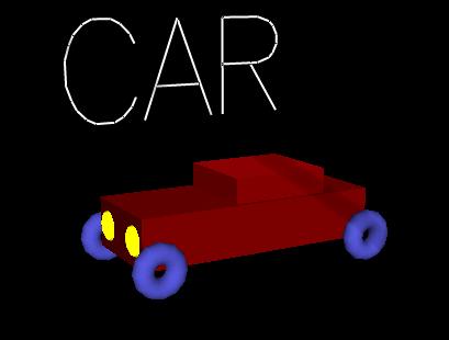
In lab 7, you created a wireframe model that was rendered using the basic color rendering model. In this lab, you should convert your model to solid objects that are rendered using lighting and materials. If you prefer not to work with your own model, you can use my wireframe car instead. If you want to do that, use a copy of the file /home/cs324/open_gl_wireframe_starter.cc. The image at the right shows the car model after it has been converted:
Whether you use this file or your own, follow the following steps:
Step 0: This is already done in the wireframe starter program. Three-D graphics in OpenGL depends on the depth buffer to do hidden surface removal. You have to request that this buffer be created in the glutInitDisplayMode function at the beginning of the main program. The function call should read:
glutInitDisplayMode(GLUT_RGBA | GLUT_DOUBLE | GLUT_DEPTH);
Also, you must clear the depth buffer at the same time that you clear the image. This is done by adding GL_DEPTH_BUFFER_BIT to the glClear function:
glClear(GL_COLOR_BUFFER_BIT | GL_DEPTH_BUFFER_BIT);
Step 1: This should have been done in the wireframe starter, but wasn't. Even though you have a depth buffer, it's not used unless you enable it by calling
glEnable(GL_DEPTH_TEST);
You should add this to the code. A good place to do it is in the init() method.
Step 2: Add a call to glEnable(GL_LIGHTING). You could do this in the init() method. Alternatively, you can enable lighting only for part of your scene and disable it (with glDisable(GL_LIGHTING)) for other parts. The fact is that wireframe objects don't look very good when lit, so in my car program, I did not enable lighting when drawing the text.
Step 3: With lighting in effect, you must have a light in your scene before anything will be visible. You can use up to eight lights in OpenGL, numbered 0 to 7. A light has no effect unless it is enabled. To enable light number zero, include the line
glEnable(GL_LIGHT0);
in the init() method. Light zero is a white light by default. (Lights number one through seven are black by default. That is, they cast no light even if they are enabled. You also have to assign a color to these lights for them to have any effect.) By default, light zero is a directional light that shines down the z-axis. We'll see how to change this in class, but it's OK for this program. If you compile and run the program at this point, you might catch a glimpse of your wireframe model.
Step 4: Switch to solid objects. Change all the glutWire... objects to glutSolid... objects. (If you are clever, you will do this with a global search and replace.)
Step 5: Run your program and see how it looks. You will probably find that the object is too dark. You can fix this by adjusting the color of the light. Light colors can actually have RGB components that are greater than 1. For my program, I set the color of light 0 to (2,2,2,1). (The alpha component is required but is ignored.) To set the color of a light, you have to store the color component values in an array and pass that array to the glLight method. You can do this with the following lines in the init() method:
            float col[] = {2,2,2,1};
            glLightfv(GL_LIGHT0, GL_DIFFUSE, col);
Step 6: Your model should now look brighter, but you will notice that the colors that you assigned to the objects have been ignored. Since you have not assigned any materials to your objects, they have an ugly default gray material. Materials are usually assigned to vertices using the glMaterial function. However, here we will use a shortcut that tells OpenGL to use the usual color of an object, as assigned with glColor3f, as the basic material color for that object. This can be done with the following two lines in the init() method:
            glEnable(GL_COLOR_MATERIAL);
            glColorMaterial(GL_FRONT_AND_BACK,GL_AMBIENT_AND_DIFFUSE);
After adding these lines, you should see your model rendered as colored, lit solid objects. Although there is a lot more to know about lighting and materials in OpenGL, this exercise should give you a basic idea of how it works and how it differs from the more basic rendering model.
More on Materials and Textures in Blender
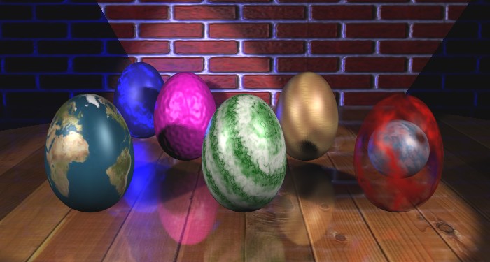
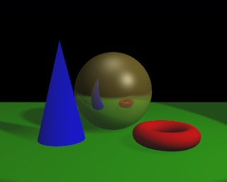
We have already been using materials and textures in Blender, but it's time to look at the subject a little more deeply. I will do this by explaining how I used materials and textures in this image:
Floor and Wall: This picture uses image textures in several places, including an image of planks on the floor and an image of bricks on the wall.
For an image texture, a two-dimensional image is applied to a surface. Blender can use many image formats, including JPEG, for image textures. To apply an image texture to an object, that object must first have a material. (The same is true for any other kind of texture.) Then, go to the Texture Buttons (F6) and click the "Image" button to indicate that you want to add an image texture. A large number of control buttons will appear, the most important of which is the "Load Image" button. When you click this, the main window will change to an image browser window in which you can find and select the image that you want to use. You can find some sample images in /home/cs324/blender/textures. Once the image has been selected, its name will be displayed next to the "Load Images" button. The texture will only be apparent in the final rendered scene, not in the interactive window. You might want to note the little "package" icon next to the image file name:
![]()
This is a toggle button. If you turn it on, then the image is saved as part of the .blend file when you save your project. If it is turned off (the default), then only the file name is saved in the .blend file. The advantage of turning it on is that when you move the .blend file to another computer, the image is carried along automatically.
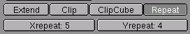 The planks image looked fine when I applied it to the floor. However, when
I applied the brick image to the wall, the bricks were much too big. I reduced
their size by using the "Xrepeat" and "Yrepeat" buttons, which are located
below the "Load Image" button. For example, by setting Xrepeat to 5, five
copies of the brick image are stretched across the wall rather than a single
copy. This makes the bricks five times smaller.
The planks image looked fine when I applied it to the floor. However, when
I applied the brick image to the wall, the bricks were much too big. I reduced
their size by using the "Xrepeat" and "Yrepeat" buttons, which are located
below the "Load Image" button. For example, by setting Xrepeat to 5, five
copies of the brick image are stretched across the wall rather than a single
copy. This makes the bricks five times smaller.
Earth Egg: The image on the egg at the front left is /home/cs324/blender/textures/earth.jpg. This image is designed to be wrapped around a sphere (or, in this case, a near-spherical object).
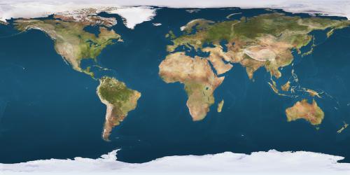
You can find similar "spherical projection" images of other planets at http://gw.marketingden.com/planets/planets.html.
 If you apply this object to a sphere or egg using the default settings,
it will look terrible. The default for an image texture is simply to
project it down onto the object. This is called a "flat" projection.
It works great for a plane, but not for a sphere and not for many
3D objects. You can change the type of projection that is used for
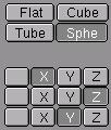
the image. The change is made in the Material Buttons (F5), not in the
Texture Buttons. Near the center of the Material Buttons window, you
will see buttons for the four texture projection types--Flat, Cube, Tube, and
Sphere. The Earth Egg was set to use Sphere projection by clicking
the "Sphe" button. The Cube projection projects 6 copies of the image from
6 directions, and is suitable for use on a cube and some other 3D objects.
The Tube projection is similar to the Sphere projection, but the north and
south pole will look different.
If you apply this object to a sphere or egg using the default settings,
it will look terrible. The default for an image texture is simply to
project it down onto the object. This is called a "flat" projection.
It works great for a plane, but not for a sphere and not for many
3D objects. You can change the type of projection that is used for
the image. The change is made in the Material Buttons (F5), not in the
Texture Buttons. Near the center of the Material Buttons window, you
will see buttons for the four texture projection types--Flat, Cube, Tube, and
Sphere. The Earth Egg was set to use Sphere projection by clicking
the "Sphe" button. The Cube projection projects 6 copies of the image from
6 directions, and is suitable for use on a cube and some other 3D objects.
The Tube projection is similar to the Sphere projection, but the north and
south pole will look different.
After I applied the Earth image to the egg using spherical projection, it was still not quite right -- the north pole was at the front of the egg instead of at the top. To fix this, I had to switch the axes used by the projection. This is done with the X, Y, Z buttons shown in the above picture.
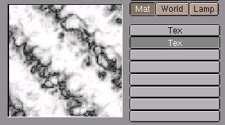 Marble Egg: It is possible to apply multiple textures to the
same object. In the texture buttons, you will see a set of eight
buttons next to the texture preview. Each of these represents a possible
texture. Click on one of these buttons to work on a particular texture.
For example, to add a second texture, click the second button and then
create the second texture as usual. In the picture, the second texture
is selected. Some textures layer naturally. A layered image texture, on the
other hand, will simply cover up the image below it unless you make the
image texture somewhat transparent. We will see later how to do this.
Marble Egg: It is possible to apply multiple textures to the
same object. In the texture buttons, you will see a set of eight
buttons next to the texture preview. Each of these represents a possible
texture. Click on one of these buttons to work on a particular texture.
For example, to add a second texture, click the second button and then
create the second texture as usual. In the picture, the second texture
is selected. Some textures layer naturally. A layered image texture, on the
other hand, will simply cover up the image below it unless you make the
image texture somewhat transparent. We will see later how to do this.
For the marble egg at the front center, I applied two different marble textures. This layering works well because a marble texture simply adds some bands of color to the object. It's possible to layer a second set of color bands on top of the first. The basic egg color is very pale green. The first marble texture layers a darker green on top of this. It uses the "Sharp" and "Soft Noise" settings of the marble texture. The second marble texture is an even darker green that uses the "Sharper" and "Hard noise" settings, which gives narrower dark veins
Remember that the way textures are applied is adjusted back in the Material Buttons. The whole right-hand side of the materials button window is devoted to these texture controls:
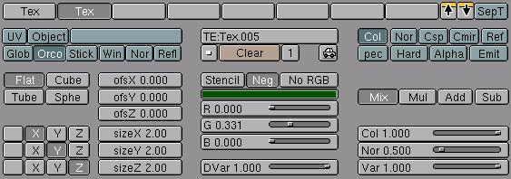
The eight buttons across the top of this picture select one of the eight possible textures that can be applied to an object. Here, two textures have been applied, and the second texture is selected. The other controls apply to this texture. If you turn on the "SepT" toggle button at the top right, you will only see the selected texture in the Materials preview; if it is off, you see the effect of all the textures.
The picture shows how I have adjusted one of the textures on the marble egg. I have set sizeX, sizeY, and sizeZ to 2.00. These values affect the size of the texture, but for technical reasons increasing the values of the size parameters actually decreases the size of the texture. (The size values actually act like the Xrepeat and Yrepeat values in the Texture buttons.) Next to the size buttons are the color controls for the texture--here set to a very dark green. You should understand how procedural textures like marble work. The texture actually just assigns a value between 0 and 1 to each point on the object. This value can be used in various ways, but the default is to use it as a blending factor between the basic material color of the object and the secondary color that is set by the sliders shown in the picture above. (How the value is used is determined by the remaining texture controls on the right side of the above picture.) Note that I have clicked the "Neg" button above the color sliders. This inverts the texture values, so that 0 becomes 1 and 1 becomes 0. For my marble texture, it switched the texture from narrow light bands on a dark background to narrow dark bands on a light background.
Wooden Egg: The wooden egg (back right) was also created by applying two textures. In this case, two copies of the wood texture were used. Both used the "Band Noise" option of the wood texture, and for the second one I set the "Turbulence" to be rather high. I also set the "sizeY" (in the Material button) for that texture to be 10, which squashed the texture down to give the small scale horizontal graininess on the egg.
Bumpy Purple Egg: The purple egg is the first example of using a texture to affect something besides color. In this case, the texture was applied to the "normal vectors" of the surface. The normal vector is used in lighting calculation to determine the direction in which the surface faces. By varying the normal vector from point to point, you can make the surface look bumpy. Note that the geometry of the surface isn't actually changed. Only the way that it affects light is changed.
![]() For the bumps on this egg, I used a "Stucci" texture, which is designed
for this purpose. Back in the Material Buttons, I turned off the "Col" toggle
and turned on the "Nor" toggle at the far right end of the window.
This says that the texture should apply to the Normals of the object
and not to its Color.
For the bumps on this egg, I used a "Stucci" texture, which is designed
for this purpose. Back in the Material Buttons, I turned off the "Col" toggle
and turned on the "Nor" toggle at the far right end of the window.
This says that the texture should apply to the Normals of the object
and not to its Color.
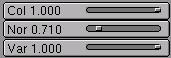 The bumps were not deep enough to satisfy me, so I wanted to increase the extent
to which the texture affects the object. This is done using the three sliders
at the bottom right of the Materials Buttons window. To increase the effect of
the texture on the normal vector, I increased the "Nor" slider from its
default value of 0.500 to 0.710. The other two sliders are used on the two
remaining eggs. (I also note that the "Col" slider can be used to make
an image texture transparent.)
The bumps were not deep enough to satisfy me, so I wanted to increase the extent
to which the texture affects the object. This is done using the three sliders
at the bottom right of the Materials Buttons window. To increase the effect of
the texture on the normal vector, I increased the "Nor" slider from its
default value of 0.500 to 0.710. The other two sliders are used on the two
remaining eggs. (I also note that the "Col" slider can be used to make
an image texture transparent.)
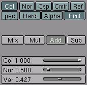
![]() Partly Transparent Egg: For the front right egg, I used a texture to make
part of the egg transparent. I also added a sphere with an image texture
inside the egg. The transparency is done with a Marble texture. However, the
texture is set to affect the "Alpha" of the object rather than the color. (This is
done in the top-right of the material buttons.) Furthermore, the texture is
set to "Mul" (that is multiply) the color value rather than to "Mix" with it.
This is done with the buttons on the middle of the right end of the Material
Buttons. Finally, I reduced the "Var" slider at the bottom right of the Material
Buttons from 1.0 to 0.8. This slider determines the extent to which the texture
affects the Alpha value of the object. When it was set to one, some parts of the
object became completely transparent. By reducing the value of the "Var" slider,
I reduced the level of transparency a bit. (One other thing: As always, to get
transparency to work properly, I clicked the "ZTransp" button in the Materials
button window.)
Partly Transparent Egg: For the front right egg, I used a texture to make
part of the egg transparent. I also added a sphere with an image texture
inside the egg. The transparency is done with a Marble texture. However, the
texture is set to affect the "Alpha" of the object rather than the color. (This is
done in the top-right of the material buttons.) Furthermore, the texture is
set to "Mul" (that is multiply) the color value rather than to "Mix" with it.
This is done with the buttons on the middle of the right end of the Material
Buttons. Finally, I reduced the "Var" slider at the bottom right of the Material
Buttons from 1.0 to 0.8. This slider determines the extent to which the texture
affects the Alpha value of the object. When it was set to one, some parts of the
object became completely transparent. By reducing the value of the "Var" slider,
I reduced the level of transparency a bit. (One other thing: As always, to get
transparency to work properly, I clicked the "ZTransp" button in the Materials
button window.)
 Glowing Egg: The glowing egg in the background is done similarly to the
partially transparent egg, except that a marble texture is used to affect the
"Emit" variable of the object rather than the "Alpha" variable. In OpenGL,
emissive color refers to color that seems to come from an object independent
of any light source. It looks like the object is glowing. In this case, using
a marble texture, I make the object look like it has bands of glowing color.
I actually played around with the settings, and decided to apply the texture
to both "Col" and "Emit," to use the "Add" method of applying the texture,
and to reduce the value of the "Var" slider.
Glowing Egg: The glowing egg in the background is done similarly to the
partially transparent egg, except that a marble texture is used to affect the
"Emit" variable of the object rather than the "Alpha" variable. In OpenGL,
emissive color refers to color that seems to come from an object independent
of any light source. It looks like the object is glowing. In this case, using
a marble texture, I make the object look like it has bands of glowing color.
I actually played around with the settings, and decided to apply the texture
to both "Col" and "Emit," to use the "Add" method of applying the texture,
and to reduce the value of the "Var" slider.
Emissive color is not really a "glow." That is, it does not cast light on other objects in the scene. To make my glowing egg look like it is illuminating other objects, I placed a blue light in the middle of the egg. It is this light that is actually generating the blue illumination.
Bonus Info: Environment Maps
 Environment maps are used to simulate reflection of the scene in a shiny object. Blender does
environment mapping by making six images of the scene -- one view in each direction from the
position of a specified reference object (or, more precisely, from the center point of the
reference object.) These scenes are then used as a texture on the
reflective object.
Environment maps are computed automatically in blender, once the parameters are set up.
If you are doing an animation, you can even have blender compute a new environment map
for each frame. The blender file for this image is /home/cs324/blender/env.blend.
(Note that you are not required to use environment maps in this lab.)
Environment maps are used to simulate reflection of the scene in a shiny object. Blender does
environment mapping by making six images of the scene -- one view in each direction from the
position of a specified reference object (or, more precisely, from the center point of the
reference object.) These scenes are then used as a texture on the
reflective object.
Environment maps are computed automatically in blender, once the parameters are set up.
If you are doing an animation, you can even have blender compute a new environment map
for each frame. The blender file for this image is /home/cs324/blender/env.blend.
(Note that you are not required to use environment maps in this lab.)
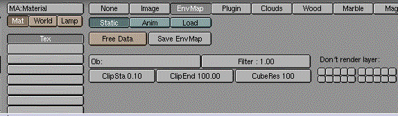
For a typical curved solid object like a sphere, you can use the object itself as the reference object. This will not give a geometrically perfect result, but it will probably look good enough. To use an environment map on a sphere, for example:
- Select the sphere, make sure it has a material, go to the Texture Buttons, add a new texture to the sphere, and set the type of the texture to "EnvMap". You will see the Environment Map controls, which are shown below.
- In the button labeled "Ob:", enter the name of the sphere. (The name is probably "Sphere" if it is the only sphere in the scene. To find the name of an object, select the object and go to the Edit buttons (F9). The name is listed in a button labeled "OB:name" at the top of the Buttons window. Click this button if you want to change the name.)
- In the environment map controls, you will probably want to increase the "CubeRes" to 250 or more. This determines the size of the images created for the environment map. If it's too small, the reflection will be blurry.
- You have to go back to the Material Buttons and make some changes. Change the texture coordinates from the default "Orco" to "Refl". For the texture mode at the right end of the Material buttons, turn off the default "Col" and turn on "Cmir". If you render now, the sphere should look like a perfectly reflective mirror.
- To blend the environment map into the sphere's material, rather than replacing it, you can turn down the value on the "Col" slider at the bottom right of the Material Buttons.
- If you edit the scene, a new environment map will not be computed automatically. To force a new computation, go to the Texture Buttons and click the "Free Data" button in the environment map controls. To automatically recompute an environment map for each frame of an animation, click the "Anim" button.
The procedure for environment mapping a plane is the similar, except that you will not get good results using the plane itself as the reference object. Instead, you should use an Empty as the reference object and position it on the other side of the plane from the camera. Ideally, it should be at the exact position of the reflection of the camera in the plane (this would make the direct view from the reference point be the same as the reflected view from the camera). You can try to judge the position of the Empty reference object by eye, but this procedure below tells you how to get it exactly right if you want to be picky:
- Choose a view in which the plane is perpendicular to the screen, so you see it edge-on.
- Select the camera by right-clicking on it. Hit Shift-S (the "snap" command), and choose to snap "Curs->Sel" to snap the 3D cursor to the camera position.
- Add an empty object to the scene. It appears at the camera position.
- Select the plane by right-clicking on it. Hit Shift-S and choose "Curs->Sel". The cursor jumps to the plane.
 Set the reference point for scaling to be the cursor, rather than the center of
the object. To do this click the small button in the 3D window header shown at the right.
Set the reference point for scaling to be the cursor, rather than the center of
the object. To do this click the small button in the 3D window header shown at the right.
- Select the empty object by right-clicking it. Without touching the mouse, hit the "S" key to start scaling, the "Y" key to reflect the empty through the plane, and the "Return" key to finish the scaling. The empty object should now be exactly on the opposite side of the plane from the camera.
- Use the Empty as the reference object by entering its name (probably "Empty") in the "Ob:" button in the environment map controls.
There is a problem with using the Empty as the reference object instead of the plane: The plane will be part of the reflected environment! You have to tell the program to not render the plane as part of the environment. This is what the "Don't render layer" part of the environment map controls is for. Move the plane to layer 2 and select layer 2 in the "Don't render layer" buttons. Since you do want the plane to be in the final image, you need to set two layers to be displayed in the image and in the 3D Window. Do this by shift-clicking the appropriate layer button in the 3D window's header (or simply by hitting CONTROL-SHIFT-2).
Once this is done, you can proceed as above for the sphere: Set the appropriate values in the Materials buttons and render the image.
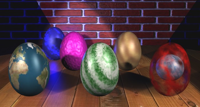
Here is another version of the eggs scene, with an environment map added, making it look as though the eggs and brick wall are reflected in a shiny floor: