CPSC 324, Spring 2004
Lab 9: Blender Advanced Modeling
IN THIS LAB, you will learn about some of the more advanced modeling techniques in Blender, including hierarchical models, extrusion, lathing, subsurfaces, and dupliverts.
Exercise 1: Make a hierarchical model of a car, airplane, motorcycle, train, or boat in Blender. Make all the components of the object children of one main component (or of an empty object). Make an image of your object displayed in a nicely lit scene, or show it in a simple animation. Try to do a nice job of the modeling. For example, use extruded curves or subsurfaces for some of the pieces. Try adding some lights, such as the headlights of a car or the underwing lights of an airplane. Save the Blender project in a file and make it available in your account so that I can check on the modeling. Put your scene or animation on your web page. Don't forget to include a discussion of how it was made.
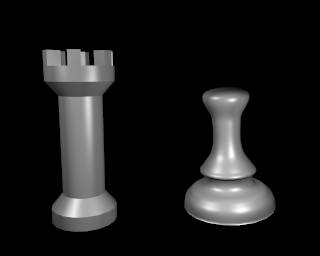
Exercise 2: Create either a rook or pawn using extrusion or lathing, as described below. Your objects must have the correct shape, but you can apply any material you like. Exhibit your object in a nicely lit scene, including a spotlight and shadow. Consider using Dupliverts to show multiple copies of your object.
Hierarchical Graphics in Blender
In hierarchical modeling, an object is built up out of several simpler objects, where the simpler objects can themselves be built up from even simpler objects. The important point is that objects created in this way can be treated as single objects. Transformations can be applied to the object as a whole, and the object can be animated as a whole. But the pieces of the object can also be transformed or animated within the object.
 In Blender, hierarchical objects are constructed using the parent
relationship. To make one object a parent of another, right-click the
child object to select it, then shift-right-click the parent. Hit
CONTROL-P, and confirm that you want to make a parent. The child object
will be connected to the parent by a dotted line. You can clear the
parent relationship by selecting the child object and hitting ALT-P.
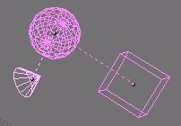
A child of one object can be a parent of another. In the picture, the
sphere is the child of the cube, and the cone is the child of the sphere.
In Blender, hierarchical objects are constructed using the parent
relationship. To make one object a parent of another, right-click the
child object to select it, then shift-right-click the parent. Hit
CONTROL-P, and confirm that you want to make a parent. The child object
will be connected to the parent by a dotted line. You can clear the
parent relationship by selecting the child object and hitting ALT-P.
A child of one object can be a parent of another. In the picture, the
sphere is the child of the cube, and the cone is the child of the sphere.
A transformation or animation that is applied to a parent object also applies to its children. However, a transformation or animation applied to a child object only affects the child, and it affects the child relative to the parent. Thus, in the picture, if the cube is resized, the sphere and cone will be resized along with it. If the sphere is moved, the cone (a child of the sphere) will move along with it, but the cube (a parent of the sphere) will not. If the wheels of a car are modeled as child objects of the car body, you could apply a rotation animation to the wheels and a translation animation to the car body. The wheels would rotate even as they are moving along with the car body.
Note: If a complex object does not have a natural "main component," you can parent all the components of the object to an empty object. Also, you can parent a camera to an object, so it's easy to make a camera that represents the viewpoint from a moving object.
Extrusion and Lathing
 Next, we look at two techniques for modeling objects that are not made up of
simple things like cubes and spheres. The techniques are called
extrusion and lathing. Extrusion is the more useful of these, and
is also a lot easier than lathing in Blender. Extrusion can be used to make
the rook shown at the right, while lathing was used to create the pawn.
Next, we look at two techniques for modeling objects that are not made up of
simple things like cubes and spheres. The techniques are called
extrusion and lathing. Extrusion is the more useful of these, and
is also a lot easier than lathing in Blender. Extrusion can be used to make
the rook shown at the right, while lathing was used to create the pawn.
To begin, try a simple extrusion. Start with a new scene and add a cube. In edit mode, select all the vertices on one face of the cube. Hit the "E" key. You will get a pop-up where you can confirm that you want to extrude. When you do this, the selected vertices are duplicated, and you will find yourself in grab mode. Move the mouse (or use the arrow keys) to position the new vertices, then left-click or hit return to end grab mode. At this point, you can use the "S" key to scale the selected vertices, if you want. Then hit the "E" key to extrude again. Move the new vertices and scale them. You might want to rotate the view and use shaded mode ("Z" key) to see the full effect. Now, you could go back and select a different set of four vertices, on the side of the object, and extrude them once or twice. If you do this a few times, you can get an interesting branching structure. Also, note that you can subdivide a face of an object by selecting the vertices of that face, going to the Edit Buttons (F9), and hitting the "Subdivide" button.
Now that you've had some experience with extrusion, you can try to make a rook. Start with a Mesh circle with 18 vertices. (The number is important.) In edit mode, make sure all the vertices are selected, and do an extrude by hitting "E". But then hit Return immediately, since you don't want to move the vertices. Instead, hit the "S" key and scale the new vertices to get a flat ring shape made up of 18 little quadrilaterals. We will first use this ring to make the six blocks on the top of the rook. (At first, I tried doing this as the last step, but I had trouble selecting the right vertices after the rest of the rook was made.)
Deselect all the vertices by hitting "A" once or twice, then select the vertices that will be extruded to make the six blocks: Select four vertices around one of the quadrilaterals. Then skip the next two vertices in the ring. Then select another four vertices. And so on. Switch to a side view (Keypad-3) and do the extrude. Move the new vertices upwards about 1 unit. (Hold down the control key or click the middle mouse button to make sure the vertices are moved directly upwards, with no sideways displacement. Alternatively, use the arrow keys to move the vertices instead of the mouse.) Rotate the view to see what you've made, if you want.
Now, you should select just the original vertices in the ring. (This is easy to do with a box select in the side view.) Still working in the side view, extrude them directly downwards five times. After the second extrude, scale the vertices down to make a smaller circle, and after the fourth extrude scale them back up. You have your rook!
Now, you might wonder why my rook has nice smooth sides while yours is faceted. If you use the "Set Smooth" button on the rook, it will look really terrible, because blender will try to smooth edges that should really look sharp. For my rook, I first turned on the "Auto Smooth" option in the Edit buttons and then hit "Set Smooth". Blender will then smooth only those faces that meet at a relatively small angle, without trying to smooth the sharp edges between faces that meet at a large angle. (The cutoff angle is specified by the "Degr" button below the "Auto Smooth" button.) Unfortunately, you will only see this smoothing in the final rendered image, not in the preview, and whether it works well depends on the exact shape of your rook -- the angles between the "layers" on the rook must be larger than the cut-off angle.
 To model a pawn, you can use lathing. Lathing refers to rotating a curve around a line
to generate a surface of revolution. Lathing in Blender is a touchy process, and it is
unlikely that you will memorize the exact steps that you need to go through. If you
want to make the pawn, follow the steps carefully.
To model a pawn, you can use lathing. Lathing refers to rotating a curve around a line
to generate a surface of revolution. Lathing in Blender is a touchy process, and it is
unlikely that you will memorize the exact steps that you need to go through. If you
want to make the pawn, follow the steps carefully.
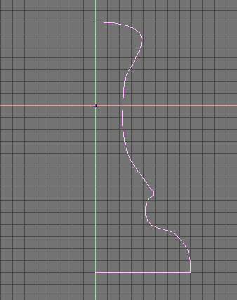
To begin, start working in the top view (Keypad-7). Hit SHIFT-C, which will move the 3D cursor to (0,0,0). It's important that the 3D cursor lie in the xy-plane, since we need to draw a curve that lies exactly in that plane. Add a Bezier curve. Extend it (by selecting one endpoint and using CONTROL-left-mouse) and shape it into half of the outline of a pawn -- something like the picture. I used snap-to-grid (SHIFT-S) to get the two endpoints exactly on the y-axis -- select the endpoint, hit SHIFT-S, and choose "Sel -> Grid" from the pop-up menu to say that you want to snap the selected object to the grid. (This is also important!) To make the sharp corner at the bottom right, I selected the control point there and hit the "V" key to make it into a corner. We are going to spin this curve around the y-axis to make the pawn.
Exit from edit mode. Select the curve and hit ALT-C. You will be asked if you want to convert the curve into a mesh. Confirm this. This is important, since lathing only works on meshes.
Now, left-click near the y-axis and use snap-cursor-to-grid (SHIFT-S again) to make sure that the 3D cursor is exactly on the y-axis. The 3D cursor specifies the line that we will spin the curve around.
Select the curve and go back into edit mode. Select all the vertices in the curve. Switch to a front view (Keypad-1) so that the y-axis will be perpendicular to the screen, and go to the Edit buttons. Find the button labeled "Spin". In the row of buttons beneath the Spin button, change the Degr to 360 and steps to 20. (The 360 says you want to spin the curve in a complete circle. The 20 says you want to make 20 copies of the curve as it spins.) Now you are ready to do the lathing: Click the spin button. If all has gone well, you will now have a nicely shaped 3D pawn. (If you have more than one World Window, then when you click the "Spin" button, the cursor will change to a question mark and you will have to click on the World Window where you want to do the lathing.)
There is one problem with lathing in blender: You get an extra set of vertices at the final position, and this can make an unsightly seam in the object. To eliminate this, in edit mode, select all the vertices in the pawn. Then click the "Rem Doubles" button in the Edit buttons. This will remove the extra vertices by combining any pair of vertices that are very close together.
As a final step, hit the "Set Smooth" button to give the pawn a smooth rather than faceted appearance. (This might work better if "Auto Smooth" is used. I forgot to do this, so the base of my pawn is not quite right.) That should do it. As you can see, lathing is a complicated affair, but the results can be very nice.
SubSurfaces
 One cool feature of Blender is something it calls "subsurfaces."
This feature uses a mesh object (generally with a relatively small number of
faces) to establish the basic shape for a more nicely curved surface inside the mesh.
In effect, the mesh acts as a set of control points for this surface, and it's only the surface
that is drawn.
One cool feature of Blender is something it calls "subsurfaces."
This feature uses a mesh object (generally with a relatively small number of
faces) to establish the basic shape for a more nicely curved surface inside the mesh.
In effect, the mesh acts as a set of control points for this surface, and it's only the surface
that is drawn.
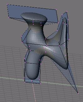
The picture shows a subsurface inside the mesh object that defines it. The picture is in Edit mode. The vertices that define the mesh are only visible in Edit mode. The mesh in this case was created by starting with a cube and doing various extrusions, as described in the beginning of the previous section. I also grabbed and dragged some individual points on the mesh.
![]() To use a mesh object for a subsurface, select the object and go to the Edit buttons (F9).
Find the button named "SubSurf", and click it. You should see the subsurface appear
inside the mesh. The two numerical buttons below the "SubSurf" button are very important.
They control the number of subdivisions applied to the surface, which in turn determines
how smooth it will be. The button labeled "Subdiv:" controls the number of subdivisions
when the object is displayed in Blender's window. The unlabeled button next to it (with
the value "4" in the picture) is much more important, since it controls the number
of subdivisions that are applied when the scene is rendered. The number should be
set to at least 3. Note that if the value is zero, you will just see the original
mesh when you render the scene!
To use a mesh object for a subsurface, select the object and go to the Edit buttons (F9).
Find the button named "SubSurf", and click it. You should see the subsurface appear
inside the mesh. The two numerical buttons below the "SubSurf" button are very important.
They control the number of subdivisions applied to the surface, which in turn determines
how smooth it will be. The button labeled "Subdiv:" controls the number of subdivisions
when the object is displayed in Blender's window. The unlabeled button next to it (with
the value "4" in the picture) is much more important, since it controls the number
of subdivisions that are applied when the scene is rendered. The number should be
set to at least 3. Note that if the value is zero, you will just see the original
mesh when you render the scene!
Don't forget that to avoid a faceted appearance on a mesh object, you should select the object (while not in Edit mode) and hit the "Set Smooth" button in the Edit buttons window.
Duplicating Objects
To duplicate an object in Blender, just select the object and hit SHIFT-D. A copy of the object is created in exactly the same place as the original object. The new object will be in drag mode, so you should immediately move it by dragging the mouse and hitting the left mouse button. If you select a group of objects, all the objects in the group will be duplicated including any parent/child relationships among the objects.
![]() If the object that you duplicate has a material, that material will not be copied.
Instead, the two objects will share the same material. That is, if you change the
properties of the material on one object, the material on the other object will
change as well. This might not be what you want. To fix the problem, select one of the objects and
go to the material buttons (F5). At the top of the material buttons window, near the right
end, find the "MA" button, as shown above. It is labeled with the name of the material,
usually something like "Material" or "Material.001" but here changed to "Red".
Next to the MA button is a number that appears only if the material is shared by
several objects. In the picture, the "2" indicates that the "Red" material is shared
by two objects. If you click the number, you will be asked if you want make the
material "Single User." If you confirm this, the selected object will get its own
copy of the material. You can then change that material without changing the material
on the duplicate object.
If the object that you duplicate has a material, that material will not be copied.
Instead, the two objects will share the same material. That is, if you change the
properties of the material on one object, the material on the other object will
change as well. This might not be what you want. To fix the problem, select one of the objects and
go to the material buttons (F5). At the top of the material buttons window, near the right
end, find the "MA" button, as shown above. It is labeled with the name of the material,
usually something like "Material" or "Material.001" but here changed to "Red".
Next to the MA button is a number that appears only if the material is shared by
several objects. In the picture, the "2" indicates that the "Red" material is shared
by two objects. If you click the number, you will be asked if you want make the
material "Single User." If you confirm this, the selected object will get its own
copy of the material. You can then change that material without changing the material
on the duplicate object.
Dupliverts
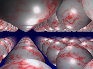 If you want a lot of copies of some object, consider using
"Dupliverts." Dupliverts makes it possible to place a copy
of an object at every vertex of a mesh object.
In the picture, the duplicated object is a sphere. The mesh object
that is used as the parent was made by scaling up a Plane object,
subdividing it several times, and then extruding all the vertices
once, perpendicularly to the plane. (To subdivide the plane,
select it, go into Edit mode, select all the vertices of
the plane, go to the Edit buttons, and click on the "Subdivide"
button.) I also added some Mist in the World buttons to make
the spheres seem to fade out with distance.
If you want a lot of copies of some object, consider using
"Dupliverts." Dupliverts makes it possible to place a copy
of an object at every vertex of a mesh object.
In the picture, the duplicated object is a sphere. The mesh object
that is used as the parent was made by scaling up a Plane object,
subdividing it several times, and then extruding all the vertices
once, perpendicularly to the plane. (To subdivide the plane,
select it, go into Edit mode, select all the vertices of
the plane, go to the Edit buttons, and click on the "Subdivide"
button.) I also added some Mist in the World buttons to make
the spheres seem to fade out with distance.
To use dupliverts, make the mesh object the parent of the object that you want to duplicate. Then select the parent object only, go to the Animate buttons (F7), and click the "Dupliverts" button. (I don't know why Dupliverts is in the Animate buttons window, since it's not an animation.) Note that the copies of the object are "virtual." Only the original object can be edited or transformed, and the changes affect all the copies. Neither the original object nor the mesh object that is used for Dupliverts is shown in the rendered image.
The Blender file for this example is /home/cs324/blender/dupliverts.blend.
Bonus Info: Transparency
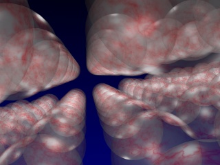 You might have already noticed that the Materials buttons window
has an "Alpha" slider to control the transparency of an object.
The default setting, with alpha equal to 1, produces fully
opaque objects. The smaller the value, the more transparent
the object.
You might have already noticed that the Materials buttons window
has an "Alpha" slider to control the transparency of an object.
The default setting, with alpha equal to 1, produces fully
opaque objects. The smaller the value, the more transparent
the object.
However, just changing the alpha value of an object's material will not give you the picture you want. You won't actually be able to see through the objects. To get this effect, you have to turn on another option in the Materials buttons. The option is called "ZTransp," and it is turned on by clicking a toggle button to the right of the Alpha slider.
The picture is a modification of the previous example in which the sphere has been made very transparent (Alpha = 0.223) and ZTransp has been turned on. In addition, the "SpecTrans" slider below the Alpha slider was set to 0.8; this makes the sphere look more like reflective glass. Also, Mist was turned off for this image, and the viewpoint was changed slightly.
Bonus Info: Multiple Cameras
If you want to be able to render a scene or animation from several viewpoints, it's convenient to have more than one camera. You can add a camera to a scene in the same way that you add other objects, but how can you render the scene from the viewpoint of the new camera?
Recall that hitting Keypad-0 shows you the scene from the point of view of the default camera. If you select an alternative camera by right-clicking it and hit CONTROL-Keypad-0, you will see the scene from the point of view of the new camera. Furthermore, that camera becomes the default camera, so that any rendering will be done from the point of view of that camera.