CPSC 424, Spring 2010
Lab 4: Introduction to Blender
BLENDER is a three-dimensional modeling
and rendering program. This means that you can use it interactively
to construct 3D "worlds" and you can render images of the worlds you
create. Blender uses OpenGL for rendering. It also uses OpenGL
for drawing its user interface. The interface has to be called
unusual. You should not expect to be able to start up Blender and
figure out what to do with it! However, the interface is fairly
usable once you get experienced with to it.
Blender can make animations, but we won't be doing anything
with animation in this lab. It can also be used to create simple
interactive games. However, we won't be doing anything interactive
with Blender games in this course. In general, there are many, many parts of
the interface whose function you won't understand (and in many
cases, I don't understand them either).
The main Blender web site is www.blender.org.
You can find information on the program and on the Blender user community
at this site, and there is a variety of
tutorials.
An html copy of the Blender 2.3 Guide -- somewhat outdated -- is at
http://www.blender.org/documentation/htmlI/.
However this lab sheet should contain all the information that you need
to get started.
Running Blender
 Blender is installed on the computers in the lab. The Blender interface uses the
numerical keypad, so I suggest that you choose a computer that has a full-size
keyboard. You can find Blender in the "Graphics" section of the application menu.
You can start it in either Full Screen or Windowed mode.
If you use Gnome, you must turn off "Visual Effects" (under "Preferences" /
"Appearance", in the "Visual Effects" tab); otherwise the effects will interfere with
Blender and make it unusable.
Blender is installed on the computers in the lab. The Blender interface uses the
numerical keypad, so I suggest that you choose a computer that has a full-size
keyboard. You can find Blender in the "Graphics" section of the application menu.
You can start it in either Full Screen or Windowed mode.
If you use Gnome, you must turn off "Visual Effects" (under "Preferences" /
"Appearance", in the "Visual Effects" tab); otherwise the effects will interfere with
Blender and make it unusable.
When Blender starts, the majority of the screen is filled with a "3D View"
that gives a view of a three-dimensional world. Below the 3D View window
is a Buttons Window, which will be discussed below. A 3D scene in Blender can contain
objects, lights, and cameras. The view in the 3D Window also contains a grid
and a "3D cursor." These are not part of the world,
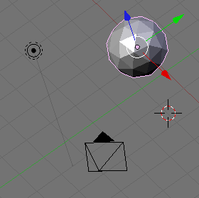
just part of the user interface. The picture at the right shows
part of the world after some modifications. At the top right is an object, an "icosphere".
It is outlined in pink, and it has its own set of axes because it is the current
selection. At the bottom is a camera. The view has been rotated to
show that the camera appears as a pyramid with an arrow to show which
direction is the top of the camera. When you render an image, the image
shows the view from this camera. The small item at the top left is a lamp,
which can provide lighting for the scene.
The 3D cursor is the other object, on the right side of the image.
Changing the View
The 3D View window shows you a two-dimensional projection of a
three-dimensional world. You need to be able to change the view,
to look at the world from a different viewpoint. This can be done
using the mouse or using the keys on the numeric keypad. (The keypad
is the group of keys on the right of the keyboard.)
This table tells you how. Keyboard commands are sent to the currently
selected window. To make sure they are sent to the 3D View window,
click on that window.
| Changing the View with the Mouse |
| Drag with middle mouse button
-- Rotate the view. (A rotated view might look cool, but it's
not necessarily best for modeling.) |
| Hold down Shift, and drag with middle mouse button
-- Translate the view (up, down, left, right). |
| Hold down Control, and drag with middle mouse button
-- Zoom the view. Move mouse up to zoom in, down to zoom out. You can also zoom in and out with th scroll-wheel
feature of the mouse. (This is very annoying on the iMacs in the lab when you
are trying to use the middle button for some other reason.) |
| Changing the View with the Keypad |
| Keypad 0 |
View from the camera. Hit 0 again to return to the regular view. |
| Keypad 7 |
Default view (from "above") |
| Keypad 1 |
View from "front" |
| Keypad 3 |
View from "side" |
| Keypad 2,4,6,8 |
Rotate the view. |
| Keypad +,- |
Zoom in and out. |
| Keypad 5 |
Switches between "orthogonal" and "perspective" projection.
(Orthogonal, the default, is generally best for modeling, but perspective
is closer to what to you would actually see.) |
Adding, Selecting, and Deleting Objects
Changing the view does not modify the contents of the world.
To do that, you have to add objects to the world. This
is where the 3D cursor comes in. A newly added object is
always added to the world at the position of the 3D cursor.
You have to position the 3D cursor before adding the object.
The 3D cursor is positioned by clicking, with the left mouse button,
on the world window. The 3D cursor is positioned in three-dimensional
space. You can't tell where it is by looking at the world from one
point of view. Typically, you would check the position of the 3D
cursor from several viewpoints by using the Keypad 1, 3, and 7 keys
to switch between viewpoints.
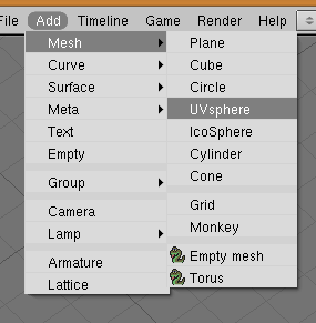 Once you have the 3D cursor in position, use the "Add" menu
to add an object to the world. Click on "Add" in the menu bar, then
click on "Mesh" in the menu. This gives a sub-menu containing
various mesh objects. ("Mesh" just means that it's made up of
polygons.) Stick to mesh objects for now. The picture at
the right shows the "Add" menu being used to add a "UVsphere."
A UVsphere is a sphere divided by lines of latitude and longitude.
An ICOsphere is divided into triangles. A Plane is actually just
a rectangle. (When you first start Blender, the default world
that you see contains a Mesh Cube as its only object.)
Once you have the 3D cursor in position, use the "Add" menu
to add an object to the world. Click on "Add" in the menu bar, then
click on "Mesh" in the menu. This gives a sub-menu containing
various mesh objects. ("Mesh" just means that it's made up of
polygons.) Stick to mesh objects for now. The picture at
the right shows the "Add" menu being used to add a "UVsphere."
A UVsphere is a sphere divided by lines of latitude and longitude.
An ICOsphere is divided into triangles. A Plane is actually just
a rectangle. (When you first start Blender, the default world
that you see contains a Mesh Cube as its only object.)
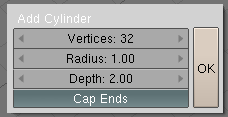 When adding certain types of objects, you will have to select a
few options. The image at the left shows the little
dialog box that shows up when you use the Add/Mesh/Cylinder command.
For a Cylinder, you have to
specify the number of Vertices, the Radius, the Depth (that is, height),
and whether or not you want to "Cap Ends".
To accept the default values, just press return or click OK.
The buttons for numerical input are examples of Blender's funny input
buttons. I'll tell you later how to change the value on such a button.
The "Cap Ends" button is for entering a boolean value. In the picture,
the option is on. If you turn the Cap Ends option off, you get a hollow
tube with no top and bottom.
When adding certain types of objects, you will have to select a
few options. The image at the left shows the little
dialog box that shows up when you use the Add/Mesh/Cylinder command.
For a Cylinder, you have to
specify the number of Vertices, the Radius, the Depth (that is, height),
and whether or not you want to "Cap Ends".
To accept the default values, just press return or click OK.
The buttons for numerical input are examples of Blender's funny input
buttons. I'll tell you later how to change the value on such a button.
The "Cap Ends" button is for entering a boolean value. In the picture,
the option is on. If you turn the Cap Ends option off, you get a hollow
tube with no top and bottom.
Objects can be selected. When you apply an edit operation
to the 3D View window, it affects the selected object or objects. In Blender,
you select an object by right-clicking it. Selected objects
are shown outlined in pink. You can select multiple objects by holding down
the Shift key as you right-click the objects. When you do this, the
little set of red/green/blue axes move to the center of the group
of objects -- and if you transform the group as a whole, the
transform is relative to this center. When multiple objects
are selected, certain operations only apply to the most recently
selected object. This object is shown in a slightly brighter pink.
To delete selected objects, just hit the X key or the Delete key.
You will be asked to confirm the deletion. You can delete the entire world, and
return to the default world, with Control-X. For these and all
keyboard commands, the command is sent to the selected window.
You can make sure that the 3d View Window is selected by left-clicking it.
As you modify the world, you can undo most operations by pressing
Control-Z, including adding and deleting objects. (Unfortunately,
Control-X doesn't seem to be undoable.)
(By the way, you can pop up a menu containing most of the
menu commands by hitting the space bar. This positions the pop-up
menu at the current mouse position, so it saves you the trouble of
moving the mouse up to the menu bar. You'll find that there
are lots of such keyboard shortcuts in Blender)
Numerical Input Buttons
Blender uses some unusual buttons for numerical input,
like the one shown above for inputting the number of vertices of
a cylinder. These are actually pretty nice. They work like this:
- Click on the left side of the button to decrease the value
by one unit.
- Click on the right side of the button to increase the value
by one unit.
- Click and drag on the button. Drag left to decrease the value,
drag right to increase the value.
- Shift-click on the button if you want to type in the value.
Press return when you finish typing.
Transforming Objects
You can translate objects (that is, move them around),
you can scale objects (this is, change their sizes), and
you can rotate objects. This is an essential part of
modeling. To apply one of these operations to the selected
object(s), use a combination of keyboard and mouse. Note that
you do not simply click-and-drag an object to move it.
| Transformations |
| Translation |
Press the "G" key. (G stands for "grab".) Move the mouse
without holding down any button. You can move the object
in the plane of the screen only. Click with the
left mouse button to finish.
Click with the right mouse button
to abort. (Hitting return will also finish;
hitting Escape will also abort.) After hitting the "G" key, you can hit
"X", "Y" or "Z" to constrain motion to one axis.
Alternatively, you can start moving an
object if you just right-click and start dragging. However,
releasing the right-mouse does not end the move! You still
have to end it as described above.
There is even a third way to start a move, with a "gesture": Click the left mouse button
and drag it a short distance in a straight line
anywhere on the 3D View Window.
The selected object -- wherever it is -- is the one that will be
dragged. The move operation begins when you release the left mouse button.
|
| Scaling |
Press the "S" key. Move the mouse towards or away from the object
to change its size. The size changes in all three dimensions.
Click with the left mouse button to finish. Click with the right mouse button
to abort. After hitting "S", you can hit "X", "Y", or "Z" to scale the
object in the direction of one axis only.
|
| Rotation |
Press the "R" key. Move the mouse to rotate the object
around a line perpendicular to the screen. Click with the left
mouse button to finish. Click with the right mouse button
to abort. If you hit "R" a second time, you can
freely rotate the object. After hitting "R", you can hit "X", "Y", or "Z" to rotate the
object about the specified axis. The default is to rotate the object about
a line perpendicular to the screen.
To start a rotation operation with a gesture,
click the left mouse button and drag it in a
circular arc anywhere on the 3D View Window. The rotation
operation starts when you release the mouse.
|
Whether rotating, scaling, or translating, you can hold the
Control key down to limit the changes, such as to integral amounts
while translating or to multiples of ten degrees while rotating.
Also, you can use the arrow keys to make small adjustments.
It is also possible to input translation, scaling, and rotation
factors numerically. To do this, hit the "N" key. ("N" stands for
numeric input.) This pops up an input box with numeric buttons
where you can set the values for the selected object.
All these operations can be applied to the camera, just as they
are applied to any other object. You can move and point the
camera to get the view of the world that you want to see when you
render an image of your world.
Note that rotations and scaling are relative to the "center" o
the object, which is shown as a tiny yellow or pink ball, with a small white
circle drawn around it. This center
point is not necessarily at the geometric center of the object.
You can get yourself real confused if you don't remember to
press the left or right mouse button to end a transformation operation.
Understanding Edit Mode
When an object is first added to the world, it is in "Edit Mode."
You can put the selected object into Edit Mode or exit from
Edit Mode by pressing the TAB key.
 In Edit Mode, the vertices of a mesh object are marked by tiny
pink or yellow balls. Edit Mode is for editing the individual
vertices of the object. In Edit Mode, you can select one vertex
or a group of vertices. Selected vertices are shown in yellow,
unselected vertices in pink.
You can apply transformations to an individual vertex or a selected
group of vertices, just as if they were objects.
When you scale or rotate a group of vertices, only the
vertices in the group are scaled or rotated. The object at right,
for example, was made from a 6-vertex cylinder by selecting the
vertices at the top of cylinder and rotating them.
In Edit Mode, the vertices of a mesh object are marked by tiny
pink or yellow balls. Edit Mode is for editing the individual
vertices of the object. In Edit Mode, you can select one vertex
or a group of vertices. Selected vertices are shown in yellow,
unselected vertices in pink.
You can apply transformations to an individual vertex or a selected
group of vertices, just as if they were objects.
When you scale or rotate a group of vertices, only the
vertices in the group are scaled or rotated. The object at right,
for example, was made from a 6-vertex cylinder by selecting the
vertices at the top of cylinder and rotating them.
When you first enter Edit Mode for a mesh object, all of its vertices
are selected. Pressing the "A" key will deselect all vertices.
If you press the "A" key when no vertices are selected, all the
vertices will be selected.) You can select a vertex by right-clicking.
Hold down the shift key while right-clicking to select multiple
vertices. There is a way to add a group of vertices to the
selection. Hit the "B" key. You can then draw a "box" by left-clicking
and dragging with the mouse. Vertices within the box are added to
the set of selected vertices. This is an easy way, for example,
to select all the vertices at the top of cylinder. You might have
to change the point of view several times while selecting the
vertices and performing operations on them.
There are a lot of things you can't do in Edit Mode,
so don't forget that you have to press the TAB key to get out
of Edit Mode.
By the way, the "A" and "B" keys can also be used outside of
Edit Mode for selecting sets of objects.
Rendering an Image
Once you have constructed a scene, you can
see a rendered image by pressing the F12 key, or by using the
"Render Current Frame" command from the "Render" menu. The scene
needs to be lit. There is one light in the default setup.
When you render a scene, a new windows opens
to show the rendered image. You can press Escape to dismiss
the window, or just click back onto the Blender window.
The objects in the world will be an ugly gray unless you
have applied materials to the objects. This is covered below.
The rendered image shows the world from the camera's viewpoint.
Remember that you can get a preview of this view by pressing
the Keypad-0 key. You can edit objects as usual in the
Keypad-0 view, which can make it easier to arrange the
objects in the image. Futhermore, you can even select the
camera and transform it while the camera view is selected!
Saving a File or an Image
Working with files is my least favorite part of Blender,
but you have to know how to do it if you want to save your
work. The "Save" and "Save As" commands in the "File" menu
are used to save complete Blender projects. This allows you
to come back later, open the file, and continue work on the same
project.
 When you save or open a file, the World Window changes into
a File Browser window. There are two lines at the top of the
window that show the directory where the file
is to be saved and the name that is to be given to the file.
You can enter these by clicking and typing. Press return to finish
typing a line. The image shows the directory and file names,
just after I have typed the file name, before pressing return.
To actually create the file, you have to press return again,
or click the "Save File" button at the top-right of the window.
When you save or open a file, the World Window changes into
a File Browser window. There are two lines at the top of the
window that show the directory where the file
is to be saved and the name that is to be given to the file.
You can enter these by clicking and typing. Press return to finish
typing a line. The image shows the directory and file names,
just after I have typed the file name, before pressing return.
To actually create the file, you have to press return again,
or click the "Save File" button at the top-right of the window.
You can also select the directory by browsing the list of files.
Similarly for the file name, if you are opening a file or if you are
saving and want to replace an existing file.
To save an image that you have rendered, use the "Save Rendered Image" command
from the "File" menu. The default is to save the image in JPEG format,
but the format can be changed. The proper file extension will be added to
the name that you provide, if you don't include it.
Before rendering the image, you can set the image size and format as well as other
rendering options. To do this, you need to use the Scene Buttons.
Press F10 to show the Scene Buttons in the Buttons Window at the bottom
of the Blender interface. (Or click the small "Scene" button at the top
of the Buttons window.) Here is some of what you should see:
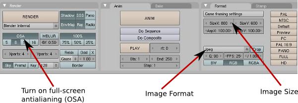
The button labeled "Image Format" sets
the format of saved images. Jpeg and Png are the only really likely options.
The numeric buttons labeled "Image Size" are used to set the size of
the rendered image.
Clicking the Render button is equivalent to hitting F12. The OSA button
is a toggle button that can be either on or off.
Here, it has been set to on. Turning OSA on enables full-screen antialiasing,
which will increase the quality
of the image, at the expense of a little more rendering time.
Other buttons in this picture control various settings for rendering
and animation.
Adding a Material to an Object
The default color of an object is gray. To change this,
you have to add a "material" to the object. This is done
using the material buttons of the Button Window. First,
you need to know more about accessing different types of
buttons. A large part of Blender's functionality is contained
in the Buttons Window, which can show many different panels
of buttons. To select a particular panel of buttons, you
can use the panel selection buttons at the top of the
Buttons window:
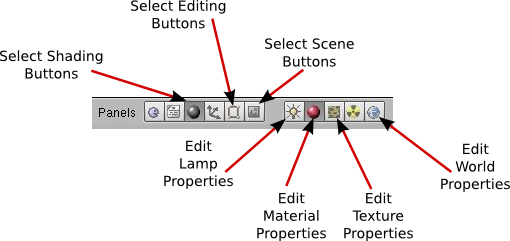
The six buttons on the left in this picture are always present. They
choose the general focus of the buttons. To work with materials and
other things that affect the appearance of objects, you want to select
the Shading Buttons. (We'll use the Editing Buttons later.)
The five buttons to the right are present when the Shading Buttons
are selected. Use these buttons to select the type of properties
that you want to edit. We start with the Material Buttons, which are
selected in the picture. You can just hit F5 to get to the material
buttons directly.
When you select the Material Buttons, you see the material properties
for the object that is selected in the 3D View window, and you can
assign a material to that object or edit its material.
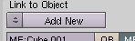 If the object does not already have a material, you won't see much
besides the "Add New" button, as shown at the right. Click this
button to add a material to the object. (You can also click the
pop-up-menu button on the left end of the "Add New" button to see a list of
materials that have already been defined. You can choose to add
one of them to the object. In that case, you can have several
objects that all use the same material.)
If the object does not already have a material, you won't see much
besides the "Add New" button, as shown at the right. Click this
button to add a material to the object. (You can also click the
pop-up-menu button on the left end of the "Add New" button to see a list of
materials that have already been defined. You can choose to add
one of them to the object. In that case, you can have several
objects that all use the same material.)
Once an object has a material, there will be lots of buttons
in the Button Window that are used to edit the material. For
now, look for the R, G, and B sliders near the left of center.
These can be used to change the color of the material.
Adding a Texture to an Object
A "texture" makes the color of an object vary from point to point.
The colors could be copied from an image, effectively painting the
image on the surface of the object. This is called an "image texture."
Alternatively, the color can be computed algorithmically from the
coordinates of the point. This is called a "procedural texture."
In Blender, a texture is part of a material. You can't add a
texture to an object unless you have already added a material,
as described above. (The default gray material that you see
on a newly created object does not count.)
To add a texture to an object, select the object. Then select
the Edit Texture Properties button (as shown in the above illustration;
or you can simply press F6). If the object already
has a texture, you will be able to edit it. Otherwise, use the
"Add New" button. Once you've
added the texture, a "Texture Type" button will appear where
you can choose the type of texture that you want to use.
And once you select the texture type, a whole new set of buttons
will appear for editing the texture.
One type of texture is an Image texture. If you choose that
type, you will see a "Load" button that you can click to select
the image that you want to use as a texture.
The remaining texture types are procedural textures.
I suggest trying "Marble", "Clouds", and "Wood".
When you select one of these, the new buttons that
appear allow you to modify the
appearance of the texture. The Marble pattern, for example,
usually looks better if it's set to "Sharp" or "Shaper"
rather than "Soft."
The Clouds, Wood, and Marble textures make patterns of
two colors. The funny thing is that both colors are
set using the Material Buttons, not the Texture buttons.
The Texture Buttons set the
pattern that the colors make, but not the colors themselves.
So, to adjust the colors, go back to the Material Buttons
by clicking the button to edit material properties (or pressing F5). One
of the colors for the texture is the basic material color, as
set by the RGB sliders in the center of the Material Buttons.
To find the other set of RGB sliders, you will have to
find the "Map to" tab, all the way to the right (and probably
not selected by default). The default second color
is an ugly magenta, so you probably want to
change it.
Adding a Light
There is already one light in the default scene, which
you can drag around so that it best illuminates your objects.
You can also add additional lights, using the "Lamp" command in
the "Add" menu. The lamp appears at
the position of the 3D cursor. You might have to
add several lamps to properly light your scene.
By default, a light acts like a point source of light.
There are several other types of light, including a "sun",
which shines from a given direction, and a "spot", which
is a spotlight. To edit a light, make sure that the "Shading
Buttons" are selected, and that the light is the selected
object in the 3D View window.
Besides changing the type of light, you can increase or decrease
the lamp's brightness (called its "intensity").
You can change the color of the light. And you can change
other properties such as the beam angle of a spotlight.
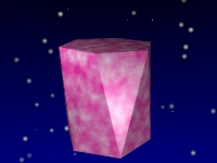
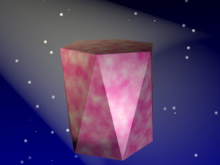
World Buttons
In addition to the objects in the world, you can set certain
global properties of the entire world. The image shown above,
of a twisted six-sided cylinder, has "stars" and a "sky" that
fades from dark blue to black. These properties are set
using the World Buttons. To see the World Buttons,
Make sure that the Shading Buttons are selected, and click
the small icon for editing world properties.
You will see RGB sliders for setting the horizon ("Ho") and zenith ("Ze")
colors. These control the color of the bottom of the sky and of the top of the sky,
but you wont see the sky gradient effect unless you also turn on the
"Blend" option (next to the preview image).
You can get stars simply by clicking the Stars button to turn that option on,
in the middle section of the World Buttons.
Finally, Facets
Mesh objects have a faceted appearance that is OK in some cases, but not
necessarily appropriate for all objects. For example, you would
probably like your spheres to be smooth rather than faceted.
To give a mesh object a smooth appearance, go to the
Edit Buttons. (You can simply hit F9.)
Select the object you want to make smooth. Then click the
"Set Smooth" button in the Button Window (at the bottom, near the left end).
You can undo the effect by clicking the "Set Solid" button.
Exercises
These exercises are due next Tuesday, February 23. They should be posted
on your web site, along with short comments (as usual). You should
also save copies of the .blend files from your projects, and turn them into
the homework folder in a folder named lab4.
Exercise 1:
The file named stage.blend contains a Blender project.
You can find a copy in /classes/s10/cs424. You should be able to open it by
double-clicking or by using the Open command in Blender.
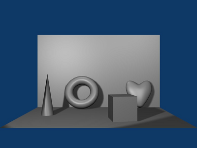
The scene in this project shows several objects on a stage, with a spotlight and shadows.
The stage is made from two Plane objects, scaled and rotated
into place. The objects and stage are the default grey color.
Add color or texture to each object and to the Planes that make up the stage.
Add a sphere and at least one more object --
maybe something hanging on the well -- to the scene.
Try to make it attractive. Here's what it looks like at the start:
Exercise 2:
Make an object similar to my twisted six-sided cylinder, and show
it nicely displayed in a well-lighted world with stars. Use different
textures and colors, but make a twisted six-sided cylinder. Here's my
image again (but I've cheated by setting up a yellowish spotlight
with "halo" effect turned on -- the halo makes the yellow glow):
Exercise 3:
Use Blender to make an image of a snowman -- with a top hat.
(It would be nice if the snowman is standing on a textured plane.)
Exercise 4:
Use Blender to make an additional image of your choice that
you believe will impress me with the amount of effort that you
have put into it.