CPSC 424, Computer Graphics, Spring 2010
Lab 6: Blender Modeling
We return to Blender in this lab for a closer look at modeling,
that is, how you can use Blender to create models of 3D objects.
The exercises for this lab will be due in a week or so. As usual,
you should post the images that you create on your course
web site, with a brief description of how you made each picture.
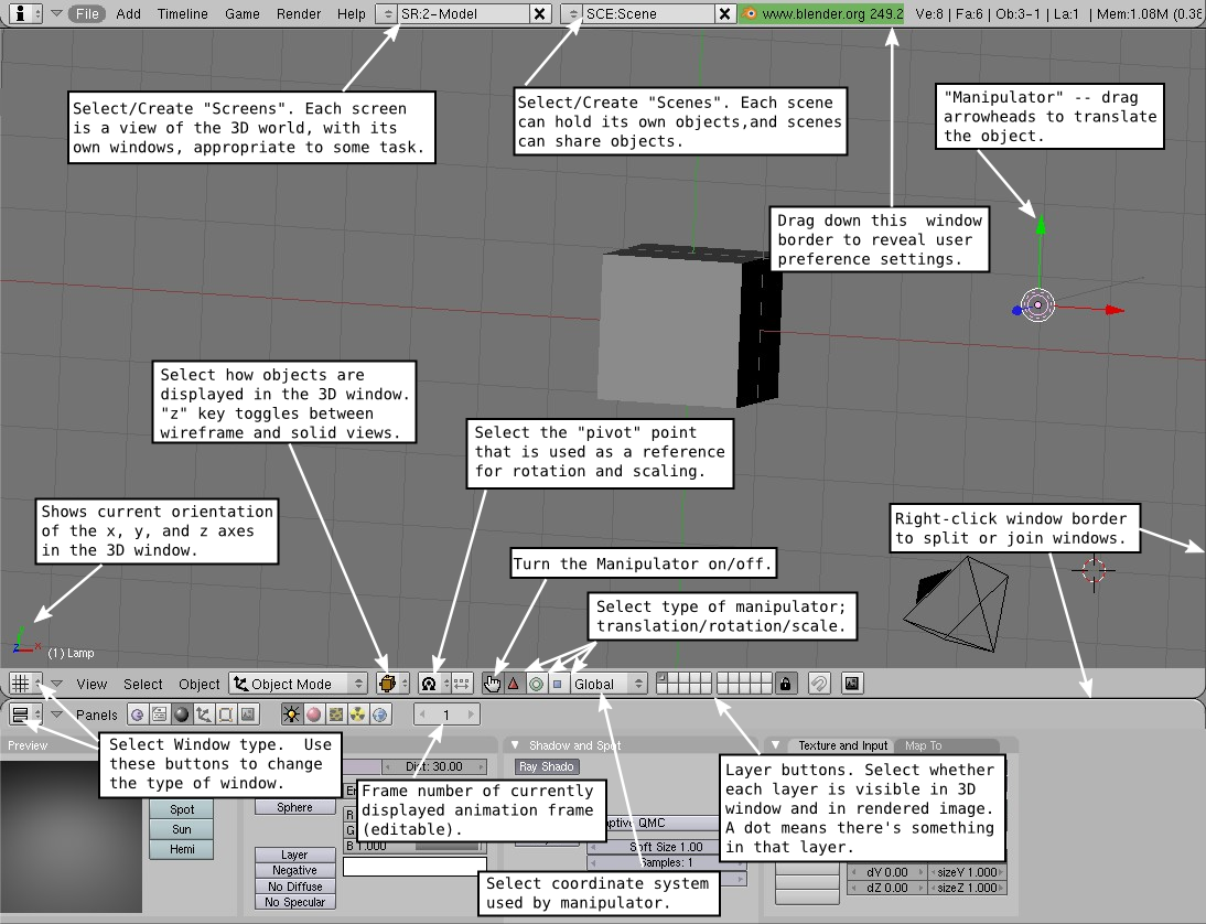
You can click here for a map of the Blender window
that might be useful.
Exercises
For this lab, you should produce four images. The first three images should
be pictures of individual objects that you have modeled. The fourth image should be
a complete scene that meets the requirements stated below. You are encouraged to
use the objects from the first three images in that scene, and to design the objects
with that scene in mind.
In addition to the images, you should complete
Lab 5 by exporting one of your objects
from Blender and importing it into Indexed Face Set program. To export an
object from Blender in OBJ format, first select the object. Then
go to "File" / "Export" and select "Wavefront (.obj)" from the long
list of export formats. You will first be asked to specify the file where
the data will be written. When you do that, a popup appears where you
can specify OBJ file options. You can turn off "Materials" under "Export,"
since that will produce an extra file that you don't need, and make sure
"Normals" is turned off (unless you have made your program read normals data
from an OBJ file). Once you have the OBJ file, you should be able to
add it to your lab5 project and have your program display it.
The Three Basic Models: Your first image should show an object
created using one or more curves. The second should show a mesh object
created using the Subsurf modifier. The third image should use transparency
and/or one of the other material or texture features described in the last section
of this lab.
The Final Scene: To give you something definite to aim for, here
are some requirements for your final scene: It should have some terrain,
created from a flat grid with the Displace modifier and/or mesh editing. Flying over
the terrain, there should be a line, a two-dimensional array, or some other formation
of identical objects made using the Array modifier. The basic flying object
should be a model of something real such as an airplane, a hot-air
balloon, or some sort of flying creature. The flying objects should cast
visible shadows on the terrain. Finally, you should add some extra interest
to the terrain, either by adding some extra objects (houses or windmills or animals, for
example) or adding some variety to the terrain itself (water or vegetation, for example).
You should pay attention to the lighting. You will probably need more than one
light to get good illumination, but maybe only one of them should cast shadows --
unless, of course, you are on a world with multiple different-colored suns...
More Background
Lab 4 covered a lot of basic ground about
Blender, but before looking at more advanced modeling, there is a little more background
information that will be useful...
Start-up Configuration:
If you would like a different start-up configuration for Blender, instead of the
default, set up Blender any way you like it, and press CONTROL-U (or use "File" /
"Save Default Settings"). You will be asked to confirm that you want to
save user defaults. You can get the original startup configuration back with
"File" / "Restore Factory Defaults" (then you still have to use CONTROL-U to
save the configuration).
Duplicating; Data versus Object:
An object on the screen has two aspects: The basic data for the object and the transform
that has been applied to that data. The data for a mesh, for example, would be the
coordinates of all its vertices in the mesh's own coordinate system. It also includes
the material properties of the mesh. It's possible for objects to share the same data
but have different transforms. Suppose you want to duplicate an object.
There are two ways to do it. You can select the object and hit SHIFT-D. This will make
a copy of the selected object. The copy will be in the exact same place as the
original, but will be in "grab" mode so that you can immediately move it away from
the original by moving the mouse. When you duplicate an object in this way, with SHIFT-D,
you make copies of both the object and its data. That is, you really do get a complete copy.
However, you can also duplicate the selected object by hitting ALT-D. But when you use ALT-D,
the two objects share the same data; only their transforms are different. This means
that if you go into Edit mode and change one of the object's vertices, the same changes
are applied to the other object. If you change the material on one of the objects, the
other one changes as well. On the other hand, if you transform one of the objects by
moving, changing, or rotating it, the change does not affect the copy. This type of
copy can actually be very useful -- and it can save memory since there is only one copy
of the object data.
Scene:
A "scene" in Blender is really its own 3D world. Each scene can contain unique objects,
but it is also possible for scenes to share objects. There is a menu button at the top
of the Blender window that you can use to create new scenes and to switch from one
scene to another. Use the small arrow button to the left of the SCE field. (You can
edit the contents of the SCE field to give a new name to a scene.) When you create
a new scene, you will immediately get a pop-up choice of "Empty", "Link Objects",
"Link ObData", or "Full Copy". "Empty" does what you would expect. The other three
choices make different kinds of copies of the current scene. If you select "Link Objects",
then the new scene contains the same objects as in the current scene, with the same transforms;
if you move an object in one scene, is also moves in the other one. You can then add new
objects that will be in only one of the scenes. You might use this, for example, if you
want to set up a common static background world and them make several scenes that show
different "actors" doing different things in different scenes, but with the
same environment. With "Link ObData", objects
in the two scenes share the same data but not the same transform; this lets you have
the same actors doing different things in different scenes, with the same
enviroment. "Full Copy" copies both the
transforms and data, so the scenes look the same originally, but really have nothing
to do with each other.
Layers:
Blender has layers, but they are not layered on top of each other. A layer is really
just a collection of objects. You can show and hide those objects by turning the
layer on and off. The main point is to allow you to work on objects in one layer
without being confused by the objects in the other layers. Blender has exactly 20
layers, and they are controlled by a set of 20 small buttons at the bottom of the
3D window. You can click a layer to select just that layer. You can shift-click
to select multiple layers. You can move objects from one layer to another: Select
the object and hit the "m" key. A set of layer buttons will pop up where you can
select the layer to which you want to move it.
Parenting:
Blender has a nice way of grouping objects.
One object can be a "parent" of another. When you drag, rotate, or scale the parent, all its child objects
are transformed as a group along with the parent. But child objects can still have
their own transformations within the group. Furthermore, a child of one object can be
a parent of another object, so you can do hierarchical graphics. If you want to group
several objects, and there is no obvious parent, you should consider parenting all the
objects to an empty object, made with the "Add" / "Empty" command. To create a parent
relationship, select the child object(s), then shift-click the parent to add it to
the selection. Hit CONTROL-P. You will have to confirm that you want to make a parent.
A dotted line will join the child to its parent.
To delete a parent relationship, select the child and hit ALT-P, and select "Clear Parent"
from the popup.
Tracking:
Tracking is a neat feature that is similar to parenting. In fact it is just parenting
with an extra feature: The child object always "looks at" the parent; as the child or parent
moves, the child rotates to keep the same orientation with respect to the parent.
In particular, this is a great way to direct a camera or spotlight to the desired
object -- just make the camera/object track the object. This is another place where
using an Empty as the parent makes sense; you can point the camera or spotlight at
a location without having an actual object there. And by animating the Empty, you
can make the camera or spotlight pan across the scene. To implement tracking,
select the child, add the parent to the selection, and press CONTROL-T. Select
"TrackTo Constraint" from the popup. The child will track the parent.
You can clear tracking with ALT-T.
Naming:
In Blender, objects, textures, materials, scenes, etc., all have names.
Blender assigns generic names such as "Cube.002." Sometimes, you need to know something's
name. An example is the "text on curve" feature that will be discussed
in the next section. In that case, you might want to use a more meaningful name.
Names are generally displayed in editable boxes. You can just click the box and
enter a new name. For objects, the name is displayed and can be changed in the
"Number" dialog box; to see it, select the object and press the "n" key.
A name box for the selected object can also be found among the Object buttons (F7),
in a box labled "OB" under "Objects and Links".
The Manipulator:
The red/green/blue axes that are attached to the selected object
do more than just show you which way the axes point. They are the "manipulator."
You can use the left mouse button to drag one of the arrowheads of the manipulator to
move the object along the corresponding axis. There is a button in the bar at the
bottom of the 3D window that you can use to turn the manipulator off. There are
also buttons for turning it into a rotation manipulator or a scaling manipulator.
Some Hotkeys: The "z" key toggles between a wireframe view and
a solid view of objects in the 3D window. A wireframe view can sometimes be
better for modeling. Pressing SHIFT-C will place the 3D cursor at the origin
and scale the view so that all objects are visible. SHIFT-S brings up
a "Snap" menu that can help with positioning the 3D Cursor and the current
selection.
Text
Blender can work with text, which it can render as either a flat 2D shape
or as a 3D shape with added thickness.
Add a text object to your scene with "Add" / "Text". When you put a text
object into edit mode, you can use the keyboard to edit the characters that
it contains; you will certainly want to do this, since the initial text is
just the word "Text".
You can control many of the properties of the text using the Edit buttons
(F9). The text object should be selected, but not in Edit mode.
For example, there are buttons to control whether
multi-line text is Right, Left, or Center justified. Most important, you
can select the font to be used for the text. Unfortunately, Blender has only
one pretty basic built-in font. However, it can load and work with Postscript
Type 1, True Type, and Open Type fonts. I have downloaded a few free fonts that
you can use, and placed them in /classes/s10/cs225/fonts-for-blender.
You can find many fonts in the directory /usr/share/fonts, although
it can be hard to tell what you are getting. You will find many familiar
fonts in /usr/share/fonts/truetype/msttcorefonts, a collection of
fonts freely distributed by Microsoft.
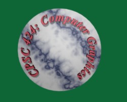 An interesting feature is that you can lay your text out along the shape of a curve.
You need a curve object, which you can create as described in the next section.
You need to know the name of the curve object -- you probably want to change the
name to something meaningful, as described above. Select the text object.
Go to the edit buttons. Enter the name of the curve object in the box labeled
"Text on Curve" (in the middle of the buttons window). The baseline of the text
will curve to match the shape of the curve. You might have to scale the text to get
it to fit nicely. Note that the text does not
jump onto the curve; it just uses the curve object's shape, whereever the
curve is located. You can move the curve itself onto a
hidden layer, if you want. If you change the shape of the curve or scale it,
the text will follow the new shape. For the sample image, I used a Bezier
circle as the curve.
An interesting feature is that you can lay your text out along the shape of a curve.
You need a curve object, which you can create as described in the next section.
You need to know the name of the curve object -- you probably want to change the
name to something meaningful, as described above. Select the text object.
Go to the edit buttons. Enter the name of the curve object in the box labeled
"Text on Curve" (in the middle of the buttons window). The baseline of the text
will curve to match the shape of the curve. You might have to scale the text to get
it to fit nicely. Note that the text does not
jump onto the curve; it just uses the curve object's shape, whereever the
curve is located. You can move the curve itself onto a
hidden layer, if you want. If you change the shape of the curve or scale it,
the text will follow the new shape. For the sample image, I used a Bezier
circle as the curve.
Once you have your text, you can extrude and bevel it, exactly as described
in the next section for curves, to get a nice 3D appearance.
Curves
Blender has two types of curves: Bezier curves and NURBS curves.
(There are also "paths", which are just a kind of NURBS curve.)
To add a curve to your scene use the "Add" / "Curve" sub-menu.
We have seen Bezier curves several times already, such as in Gimp. NURBS curves
are similar, but the curve is determined entirely by control points and isn't
constrained to pass through any particular points. NURBS curves are known for
making smooth shapes.
When you use edit mode
on a curve, you will see the control points. For a NURBS curve, they lie alonside
the curve. For a Bezier curve, the control points are at the ends of "handles"
that are attached to points on the curve. You can select control points
and drag them or otherwise transform them. For a Bezier curve, you can also
select the points on the curve and drag them. By default, the two ends of
a handle line up, making a straight line; if you move one the other moves.
To get a free handle, where you can move the control points separately and
make a corner, select the point on the curve to which the handle is
attached and hit the "H" key. Using the "H" key again will restore the
previous behavior.
More important, you can extend a (non-closed) curve by adding new points.
To do this, start with a basic NURBS or Bezier curve (not a circle). Select
the curve and go into edit mode. Select one of the endpoints and nothing else
(for a NURBS curve, select one of the control points on the end).
Now control click with the left moust button at the location where you
want to add a point. You can continue left-control-clicking to add as
many points as you want.
If you want to close the curve (that is, connect the end back to the beginning),
just hit the "C" key. Hitting the "C" key again will re-open the curve.
You can also add points in the middle of a curve. In edit mode, select two or more
consecutive vertices of a Bezier curve (or control points of a NURBS curve).
In the Edit buttons (F9), find and click the "Subdivide" button (under "Curve Tools1",
probably at the far right).
A closed 2D curve bounds a region, which will be shown as a flat surface when
you render the scene. (A non-closed curve won't be visible.) However, a
curve can actually have multiple disconnected segments. You just have to add
new curves while you are editing a curve in edit mode. The new curves
that you add will become part of the curve that you are editing. When a
curve has several segments, it's not completely clear what it means to be
inside the curve. The rule is based on "winding number" at a point,
which means the number of times that the curve encircles the point.
If the curve circles the point an odd number of times, then the point
is inside the curve; if the curve encircles it an even number of times,
then the point is outside. This means, for example, that if you add a small Bezier
circle inside a larger closed curve, you effectively cut the circle out
of the big curve.
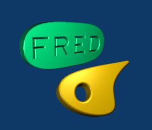 You can extend the 2D region inside a closed curve into the third dimension
by "extruding" the curve. This should be done with the curve selected, but
not in edit mode. Go to the Edit buttons (F9), and find the input labled
"Extrude." Increasing the value in this box extends the curve into 3D, perpendicular
to the plane in which it lies. Below the "Extrude" box is a "Bevel Depth" box.
Increase the value in that box to cut an edge off the 3D shape of the extruded curve.
Below that is the "BevResol" box; increasing that will round the edge rather than
cut it off level. For the lower object at the right, I put a Bezier circle inside
a NURBS curve and added Extrude, Bevel Depth, and BevResol.
You can extend the 2D region inside a closed curve into the third dimension
by "extruding" the curve. This should be done with the curve selected, but
not in edit mode. Go to the Edit buttons (F9), and find the input labled
"Extrude." Increasing the value in this box extends the curve into 3D, perpendicular
to the plane in which it lies. Below the "Extrude" box is a "Bevel Depth" box.
Increase the value in that box to cut an edge off the 3D shape of the extruded curve.
Below that is the "BevResol" box; increasing that will round the edge rather than
cut it off level. For the lower object at the right, I put a Bezier circle inside
a NURBS curve and added Extrude, Bevel Depth, and BevResol.
It's possible to make Text into a curve. Just select the
text object, hit CONTROL-C. For the purposes of this example,
select "Curve (Single filling group)" from the popup. Once you've done
this, you can edit the character outlines as curves. However, you can't convert
the curves back to text. Furthermode, in edit mode, you can add other
curve segments to the text curves. For the upper object in the image,
I created the text, converted it to a curve, put it in edit mode, added
a Bezier circle, and manipulated the vertices of the circle so that the
circle surrounded the text. Once I had that, I could extrude and bevel
as usual.
Vertex, Edge, and Face Editing
The rest of this page deals mostly with mesh modeling, and even then
it only covers a small portion of all the options that are available.
A mesh is just a connected net of polygons. You can add a mesh to your
scene using the "Add" / "Mesh" submenu, but those meshes are just the
starting point for modeling.
When you go into edit mode for a mesh object, several new buttons are
added to the bar at the bottom of the 3D window:
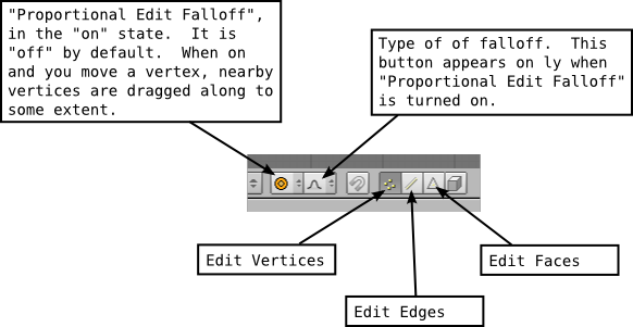
By default, when you are in edit mode for a mesh object, you edit vertices.
That is, you can select and transform individual vertices and sets of
vertices. But polygonal meshes are made up of vertices, edges and
faces. Sometimes, it's useful to work with edges or faces
in edit mode, instead of individual vertices. Use the "Edit Faces",
"Edit Edges", and "Edit Vertices" buttons to select which of the three you
want to work with.
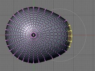 By default, when you transform selected vertices (or edges or faces) in
edit mode, only the selected items are affected. This can lead to ugly,
spiky objects! If you turn on "Proportional Edit Falloff", then a vertex exerts
a kind of force on neighboring vertices, so that if you drag a vertex,
for example, nearby vertices are pulled along with it. When this
feature is turned on, using the button shown above, and you are transforming
some vertices, a circle appears in the
3D window to show the "radius of influence", that is, the distance over which
the force exerted by a vertex extends. You can change the size of the
radius of influence using the scroll wheel on the mouse or the
"+" and "-" keys on the keypad. (On my Mac, I have to use Option +/-.)
In the image at right, a sphere is in edit mode and a group of
vertices is being dragged. The faint white circle shows the
radius of influence, and you can see that vertices within that
radius have shifted somewhat in the same direction as the
selected vertices that are being dragged. The shape that results
from this edit will be much nicer than if only the selected vertices
moved.
By default, when you transform selected vertices (or edges or faces) in
edit mode, only the selected items are affected. This can lead to ugly,
spiky objects! If you turn on "Proportional Edit Falloff", then a vertex exerts
a kind of force on neighboring vertices, so that if you drag a vertex,
for example, nearby vertices are pulled along with it. When this
feature is turned on, using the button shown above, and you are transforming
some vertices, a circle appears in the
3D window to show the "radius of influence", that is, the distance over which
the force exerted by a vertex extends. You can change the size of the
radius of influence using the scroll wheel on the mouse or the
"+" and "-" keys on the keypad. (On my Mac, I have to use Option +/-.)
In the image at right, a sphere is in edit mode and a group of
vertices is being dragged. The faint white circle shows the
radius of influence, and you can see that vertices within that
radius have shifted somewhat in the same direction as the
selected vertices that are being dragged. The shape that results
from this edit will be much nicer than if only the selected vertices
moved.
Extruding
Extrusion is a powerful method for adding geometry to a mesh.
Extrusion duplicates one or more geometry elements (vertices, edges,
or faces), with the duplicate attached to the original mesh with
more new edges or faces. The easiest way to do this is with "quick
extrude" (although it doesn't offer the most control). To use
it, put the object into edit mode and select the geometry elements that
you want to duplicate. Mostly commonly, that will mean one of the
faces of the mesh, although you can also do multiple faces or
single edges. Selecting a face means selecting all the vertices
of that face (or, you can use face editing and simply select the
face itself). Then all you have to do is CONTROL-left-click at
some point, and the selected face will be duplicated at that
point. (Note that this is the same way that you would extend
a curve.) The original face is now de-selected, and the new
duplicate face is selected instead, making it easy to move,
scale, or rotate the new face and to add more faces at other
locations.
For more control, select the geometry that you want to
duplicate and press the "e" key. A pop-up will ask you what
you want to duplicate. For example, if you have selected all
the vertices of a face, you might just want to extrude the
edges and not the whole selected region. (However, selecting
"Region" seems to work better for the subsurface modifier that
will be covered in the next section.) When you extrude
using the "e" key, the duplicated geometry is in the same
location as the original and will not be visible, but it is
selected and in grab mode so that you can easily move it away
from that location.
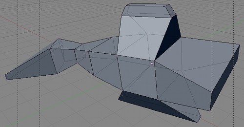
As an example, I started with a mesh cube -- often a good idea --
and extruded various faces, applying various scaling factors
along the way. Here is what it looked like in the Blender
3D window in edit mode:
Subsurf Modifier
"Modifiers" are a powerful feature that can affect the
rendered view of a mesh object, without actually modifying
the underlying geometry. To apply a modifier, select the
object, go to the Edit buttons (F9), and look for an
"Add Modifier" button (in a "Modifiers" tab, on the far right).
When you click this button, you get a menu of available
modifiers. I only understand a few of them.
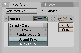 The "Subsurf" (sub-surface) modifier is very useful for modeling shapes,
particularly when used with extrusion. It makes a smoother shape that
uses the original shape as an outline. Try adding a
Subsurf modifier to a cube that you have extruded a few times.
A small panel will appear under the "Add Modifier" button with
controls for the modifier, as shown at the right. The "Levels"
and "Render Levels" are important controls for sub-surfaces.
Increasing the level increases the number of polygons on the sub-surface,
and hence its smoothness. The "Render Level" control selects the number
of levels that will be used when an image of object is rendered.
The "Levels" control selects how many levels you see in the 3D window
(which you might want to make smaller than the render level to speed
up drawing of the window). You should also note the "Apply" button,
which will discard the original surface and replace it with the
sub-surface. You might do this if you want to start editing the
sub-surface itself -- but you won't be able to get the original back
(except with Undo). The "X" above the "Apply" button can be used
to remove the modifier from the object. Here is a rendered image
produced when the a Subsurf modifier was applied to the extruded
cube from the previous section:
The "Subsurf" (sub-surface) modifier is very useful for modeling shapes,
particularly when used with extrusion. It makes a smoother shape that
uses the original shape as an outline. Try adding a
Subsurf modifier to a cube that you have extruded a few times.
A small panel will appear under the "Add Modifier" button with
controls for the modifier, as shown at the right. The "Levels"
and "Render Levels" are important controls for sub-surfaces.
Increasing the level increases the number of polygons on the sub-surface,
and hence its smoothness. The "Render Level" control selects the number
of levels that will be used when an image of object is rendered.
The "Levels" control selects how many levels you see in the 3D window
(which you might want to make smaller than the render level to speed
up drawing of the window). You should also note the "Apply" button,
which will discard the original surface and replace it with the
sub-surface. You might do this if you want to start editing the
sub-surface itself -- but you won't be able to get the original back
(except with Undo). The "X" above the "Apply" button can be used
to remove the modifier from the object. Here is a rendered image
produced when the a Subsurf modifier was applied to the extruded
cube from the previous section:
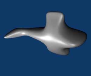
Hint: I was going after a fish shape, but I should probably have used
curve objects for fins and attached them to a fishy body.
Note: If part of the content of the Buttons window is
off-screen, you can use the middle mouse button on that
window to drag the content into view.
Displace Modifier
A "Displace" modifier moves the vertices of a mesh, with
the amount of displacement varying from vertex to vertex.
You can add a Displace modifier to a mesh in the same
way that a Subsurf modifier is added. The Displace
modifier can work well for a Sphere, where it can
add a rough, planet-like surface. For terrain,
you can apply a Displace modifier to a Mesh "Grid".
You need a lot of vertices, so make the "X Res" and
"Y Res" of the grid 100 or higher.
By default, the displacement is in the direction normal to the
surface, which should be OK. More interesting, the amount of
displacement is controlled by a texture. A procedural
texture like Marble or Clouds can work well for this. A grayscale
image can also work. (In fact, there are images that are
meant precisely for creating terrain using this technique.)
To select the texture for the Displace modifier, you need
to enter the name of the texture in the control panel for the
modifier, in the box labeled "Texture". This means that you
need a texture and you need to know its name. Unfortunately,
I don't know a way to get Blender to create a texture except
to assign one to an object. So you should assign the texture
that you want to use to some object, at least temporarily.
In the texture buttons where you specify the properties of the
texture, the name of the texture is displayed in a box
labeled "TE". You can click on the box to change the name to
something meaningful, if you want. Enter this name in the Texture
box of the Displace modifier.
You should see the effect immediately, though you might have to rotate the view
to see it clearly. You will certainly want to decrease the "Strength"
of the modifier to make the displacement effect less extreme. And you
will probably want to hit the "Set Smooth" button to get a smooth-looking
surface.
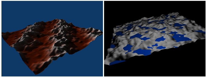
Here are two examples of Displace operators applied to Grids to produce
terrain. I used a Marble texture on the left, a Clouds texture on the
right. In both cases, I set the specular color to black to avoid having
glossy ground. On the right, I added a separate, smooth blue plane
that lies above the terrain in some places and below it in others.
On the left, I used the same texture on the Grid itself as I did for
the Displace modifier. This is a nice effect, since it makes
the color correlates with the height
Array Modifier
 Another modifier, the "Array" modifier, can make duplicates of an object
and arrange them in a line. Just add the modifier to an object, adjust
the distance between objects in the X, Y, and Z directions, and use
the "Count" control to specify how many objects you want. (There are more
advanced ways of arranging the duplicates, but I won't cover them here.)
Another modifier, the "Array" modifier, can make duplicates of an object
and arrange them in a line. Just add the modifier to an object, adjust
the distance between objects in the X, Y, and Z directions, and use
the "Count" control to specify how many objects you want. (There are more
advanced ways of arranging the duplicates, but I won't cover them here.)
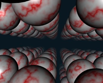
In the picture shown at the right, I started with a single sphere
and applied three Array modifiers to it. (You can add multiple
operators to an object, and they will be applied in sequence.)
The first modifier turned the sphere into a line of spheres in
the X direction. The second modifier duplicated the line in the
Y direction to give a grid of spheres. The third duplicated the
grid in the Z direction to give 3D formation if spheres.
In the image, I placed the camera in the grid, looking along a line
of spheres, with a Sun shining in the direction that the camera is
looking. I added some Mist (in the World buttons, next to the controls
that you use to add stars) to make the spheres fade a bit in the distance.
(I had to set a fairly large "Dist" value for the mist, or else I
didn't see anything at all.)
More on Lights, Materials, and Textures
There are many fun features of lights, materials, and textures that
weren't mentioned in the last Blender lab. I'll talk about a few of the
nice ones here -- some of which use Blender's built-in basic ray-tracing
abilities that can create effects that are difficult to achieve without
ray-tracing.
Lights come in several varieties. A Lamp radiates light in
all directions from a point. A Sun shines parallel rays from a given
direction. A Spot acts like a spotlight. Their properties can be
set in the Shading/Lamp buttons (F5, then click the lamp icon in the
header). There are RGB sliders for setting the color of the light
and an Energy slider that sets it general level of brightness.
There is a "Ray Shadow" button that you can click to turn on
ray-tracing-based shadows. Shadows are off for a newly created light, which means
that that particular light will not cast shadows. (However, the light in
the default Blender start-up configuration has shadows turned on.)
For spotlights, an older type of shadow algorithms, "Buf. Shadow",
is also available. Before ray-tracing, this was the only type of
shadows that were available, and only spotlights could cast
shadows.
Lighting a scene properly can be difficult. One guideline
is to try three-point lighting. This uses a light near and
a little above the camera, another off to the side and below the
camera, and a third dimmer light illuminating the scene from
behind. Note that if a light is not set to cast shadows, then
it will shine right through objects, and this is a desirable
effect in some cases.
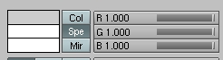
Material color is set using RGB sliders in the Material
buttons, as shown at the right. Note the buttons for Col, Spe, and Mir.
"Col" refers to the basic, so-called "diffuse" color. "Spe" refers to
the "specular" color, which determines the color of hilites where light
shines on a shiny material. (Mir is more obscure.) The specular color
is often white even for colored materials. When "Col"
is selected, the sliders affect the diffuse color. To change
the specular color, select "Spe." If you change "Spe" to black,
then the material does not have specular hilites.
There is also an "A" slider for the alpha component just below
the RGB sliders. For a transparent object, you have to
set A to be less than 1. However, the object will not
actually be transparent unless you also turn on transparency
calculations. To do this, find the "Mirror Transp" tab, further
to the right. This tab contains a "Ray Transp" button. Turn on
this option to enable ray-tracing based transparency. (You can
also get "refraction" in a transparent object. For this, set the
IOR slider to a value greater than 1 -- probably only a little
greater.)
One of the nicest things about ray-tracing is its support for
reflection of one object in another, which is very hard to do
without ray-tracing. To make an object reflective in this
sense, you have to turn on "Ray Mirror", which you will find
just next to "Ray Transp." You also need to set
the value of the "RayMir" slider to be greater than 0 to make
the surface reflective. Otherwise, you won't see any reflection
at all on the surface.
When working with textures, you should take note of the
"Texture", "Map Input", and "Map To" tabs at the far right of
the Material buttons. The "Texture" tab determines which texture
the other two tabs apply to, when there are multiple textures.
The other two tabs look like this:
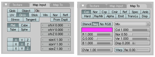
The "Map To" tab, shown on the right, tells what is done with
the texture. We have only talked about applying textures to the
color of a material, which is the default. Selecting the "Col"
button turns this behavior on and off. But the other buttons enable
other ways of using the texture data. For the most part, they
make sense mostly with a grayscale texture like the procedural
Marble and Clouds textures. Here are the options that I sometimes
find useful: "Nor" makes the texture affect normal vectors; this can give
a bumpy appearance to the surface, an effect known as a
"bump map." "Alpha" allows the texture to make parts of the surface
more or less transparent; in order to get this to work, I had to
change the selection that says "Mix", below the buttons, to "Subtract".
"Emit" affects emissive color, which makes
the surface look like its giving off light. (Note that these three
buttons are three-way switches, with states corresponding to no effect,
positive effect, and negative effect.) The sliders below the
button control properties such as the strength of the texture effect.
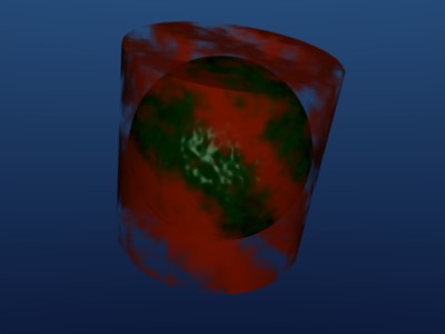
This picture shows a sphere with a bump map inside a cylinder
that has a texture affecting its alpha:
The "Map Input" tab controls how the texture's texture coordinates
map onto the surface. The "Cube", "Tube", and "Sphere" buttons can
produce better coordinates for some shapes. The "sizeX", "sizeY",
and "sizeZ" buttons affect the scaling of the texture in each direction.
The "ofsX", "ofsY", and "ofsZ" buttons offset the texture; that is,
they translate the texture along the surface.