In this week's lab, you will experiment with animation in Blender. This handout covers some basic animation techniques. You are not expected to learn all of them, but you should certainly be reasonably familiar with keyframe animation and IPOs, and you should know enough about other techniques to recognize when you might need them.
The assignment associated with this lab is to create three animations. The first should use keyframe animation of transformations (scale, rotation, and/or location). The second should use path animation. And the third should use one of the other techniques described below (particle system, lattice deformation, animation modifier, hook, or animation of lights, materials, or textures). You can use scenes from previous lab as a starting point for one or two of the animations -- maybe make the flying objects from the previous lab actually move.
Render your animations at a reasonable, small size (maybe 400-by-300) and save them as JPEG avi files. Be sure to read the next section of this page, about saving animations. Also render at least one individual frame from each animation. On your web page for this lab, post a frame from the animation, along with a link to the animation. As usual, include a short caption about how the animation was made.
![]() You should be familiar with the "Scene Buttons" (F10), which are selected using
the rightmost icon in the group of six icons shown at the right. Also make
sure that the first icon ("Render Buttons") is selected in the second group
of icons shown. The Buttons window will show a set of rendering controls,
including these two panels:
You should be familiar with the "Scene Buttons" (F10), which are selected using
the rightmost icon in the group of six icons shown at the right. Also make
sure that the first icon ("Render Buttons") is selected in the second group
of icons shown. The Buttons window will show a set of rendering controls,
including these two panels:
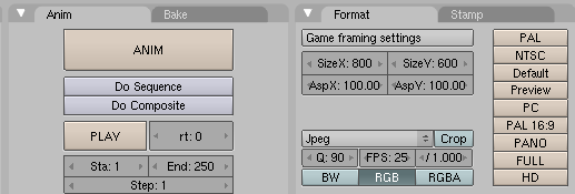
Note the "SizeX" and "SizeY" buttons, which control the size of the rendered images. For the animations in this lab, you will probably want to reduce the size to cut down on the rendering time. Also note the "FPS" button, which sets the number of frames per second in an animation. Most important is the format button, which is set to "Jpeg" by default. If you leave it at this setting, each frame of an animation will be rendered as a separate JPEG image, which is OK for some purposes, but not for publishing the animation. The same is true for other single-image formats, such as PNG. To get the animation in a single file, use the format "AVI Jpeg." The files produced by this option should be playable on most systems. (On MacOS, you should also be able to save the animation as a QuickTime movie. The FFMpeg option should make it possible to save the output in a wide variety of formats, but it doesn't seem to work on our lab computers.)
You can render an animation by hitting the "ANIM" button, shown on the left above. The range of frame numbers that is rendered is set on the "Sta" and "End" buttons, on the bottom left above. The default is for the animation to run from frame 1 to frame 250. You will want to adjust this range, especially for short trial runs.
 An animation is always saved to disk as it is rendered. The output destination
is controlled by the top input in the "Output" pane, at the far left of the
Render buttons, shown here. The default value is "/tmp/" which means that the
output will be saved in the /tmp directory. This might be OK for trial
runs, but in general, you will want to set a different output destination.
If the destination ends with a "/", then it is a directory, and the output
is stored in that directory, using a name such as "0000-0050.avi" (assuming that
you have selected the "AVI Jpeg" output format). If the destination does not
end in "/", then the last part of the destination becomes part of the file
name. Keep in mind that if the selected output format is "Jpeg", or some
other single-image format, then Blender will create a separate file for each frame
of the animation.
A basic and general type of animation uses keyframes and interpolation. In keyframe animation, a property such as location or color is assigned values for one or more frames of the animation. The frames for which values are assigned are called keyframes. Values of the property for other frames are obtained by interpolation between the key frame values (or by extrapolation to frames before the first keyframe and after the last keyframe). In Blender, interpolation uses IPO curves. An IPO curve is just the graph of some quantity as a function of frame number. The key frames define certain points on the graph. Between these points, the graph is given (by default) as Bezier curves. Blender lets you edit IPO curves in a very general way.
When working with animation, it might be a good idea to use the "Animation Screen", the first entry in the screen ("SR") menu. This screen includes an IPO window, on the right. You will need an IPO window for editing IPO curves.
![]() The current frame number is shown in a box like the one shown here at the right.
You can change the frame number by editing the number in this box.
You can also use the left/right arrow keys to move forward and back one frame
and the up/down arrow keys to move ten frames forward or back. Hitting
ALT-A will play the animation in the 3D window, until you press the ESCAPE
key -- the start and end frame for the animation are taken from the "Sta"
and "End" boxes in the Render buttons.
The current frame number is shown in a box like the one shown here at the right.
You can change the frame number by editing the number in this box.
You can also use the left/right arrow keys to move forward and back one frame
and the up/down arrow keys to move ten frames forward or back. Hitting
ALT-A will play the animation in the 3D window, until you press the ESCAPE
key -- the start and end frame for the animation are taken from the "Sta"
and "End" boxes in the Render buttons.
To create a keyframe for some quantity, go to the frame number that you want to use as a keyframe. The object that you want to animate should be selected. Adjust the quantity that you want to animate (such as by dragging, scaling, or rotating an object). Hit the "I" key to insert a key frame. A pop-up will ask you to select the quantity or quantities for which you want to insert a keyframe value. For now, stick to "Loc" (Location), "Rot" (Rotation), and "Scale". Note that you can simultaneously insert keys for several of these quantities, such as "LocRot". After inserting one keyframe, move to another frame number, and repeat the process. Do this as many times as you want. Don't forget to use the "I" key, or else the changes that you make in a frame will be lost when you change to another frame number.
In some cases, you might get an acceptable animation just by inserting some key frames. Often, though, you will want to edit the IPO curves. You can do that in the IPO window. Here is what the IPO window looked like after I inserted keyframes for "LocRotScale" at frames 1, 20, and 40. There is a separate curve for the x, the y, and the z component of the location, the rotation, and the scale. (The three scale curves are identical, so two of them are hidden behind the third.)
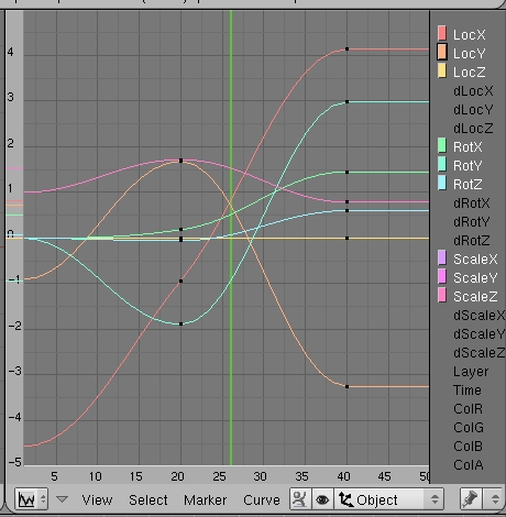
The black dots on the curves represent the key values which were inserted using the "I" key. You can select a curve by right-clicking it or by left-clicking the corresponding colored box on the right, next to the name of the quantity. You can also shift-click to select several curves. (If you click the quantity name itself, other curves will be hidden; this can be useful when editing the curve. Shift-click several names to show several curves.) When curve is selected, the black dots turn white.
You can transform the selected curve in the usual way, using the "G" or "S" key (and even the "R" key, though it's kind of strange). For example, if you want to slow down or speed up the animation, you can hit "S" followed by "X" and then drag the mouse to scale the curves in the X direction only.
You can edit the selected curve as a Bezier curve. Hit the TAB key to go into edit mode. You will see the usual Bezier handles at each point on the curve. In edit mode, you can add a new point to an IPO curve with control-left-click.
The vertical green line in the IPO window is important. It marks the current frame number. You can change the frame number by left-clicking the IPO window; the green line will jump to the point where you click. You can also drag the green line to "scrub" through the animation.
Note that the IPO window shows IPO curves for the selected object only, and that to see the IPO curves for an object, "Object" must be selected in the menu at the bottom of the screen. The "Curve" menu has several useful options, most notably the "Extend Mode" submenu. This submenu controls what happens before the first keyframe and after the last keyframe. The default is to extend the curve as a constant, using the value in the first or last frame. To change the default, select the curve and then select one of the entries in the "Extend Mode" submenu. I will leave you to experiment with the possible values...
You can animate material properties just as easily as geometric properties. To insert a key for a material property, select the Material buttons (F5). Select the object whose material you want to animate, and go to the frame number where you would like to insert a key value. Set the value of the property for that frame. For example, if you want to animate the color of the material, set the color that you want the material to have in that frame. Make sure that the mouse is over the Materials button window, and hit the "I" key. Select the appropriate property group from the popup menu. If you are animating the color, select "RGB". Repeat the process for other keyframes.
To view and edit the IPO curves for material animation, set the IPO type in the popup menu at the bottom of the window to "Material". (This is the menu that originally says "Object".)
There are many material properties that can be animated using the "I key. You can animate the "Alpha" value to make an object become more opaque or fade away with time. The "Ofs", "Size", and "All Mapping" entries in the popup refer to properties of the texture that can be viewed in the "Map Input" and "Map To" panes of the Material buttons. By animating "Ofs" (offset) or "Size", you can make a texture move around on the surface of an object.
To animate the properties of a light, select the light and go to the Lamp buttons. If you hit the "I" key while the mouse is over the Lamp buttons window, you can insert keyframes for lamp properties. In particular, you an animate the color and the energy of the lamp. To see the IPO curves for the lamp properties, set the IPO type to "Lamp" in the popup menu at the bottom of the IPO window.
Note, by the way, that you can animate the geometric properties of the lamp, such as location and rotation, by using the "I" key while the mouse is over the 3D window.
Finally, I will note that you can animate properties of the "world" such as the zenith and horizon colors by using the "I" key while the mouse is over the World buttons. You could, for example, make the sky brighten over time. To see the IPO curves, set the IPO type in the IPO window to "World".
Path animation can be used to move an object along a path. A path in Blender is a kind of curve (actually just a NURBS curve with certain properties). To add a path to a scene, use Add / Curve / Path. Recall that you can extend a path by going into edit mode, selecting one of the endpoints, and using control-left-clic to add points. Also, you can close the path by hitting the C key while in edit mode. A path has the "3D" option enabled, so that it is not constrained to lie in a plane.
To make an object follow the path, select the object by right-clicking it, then shift-right-click the path. Hit Control-P, and choose "Follow Path" from the popup. The object will be joined to the path by a dotted line. Note that the object doesn't jump to the path, but you will probably want to move it onto the path. (Suggestion: Go to frame 1, select the path go into edit mode and select the starting vertex of the path, use Shift-S / Cursor-to-Selection to move the cursor to the start of the path, leave edit mode, select the object, and use Shift-S / Selection-to-Cursor; this will position the object exactly on the path at frame 1.)
By default, the object -- actually, the point at which the object is attached to the path -- moves along the path from beginning to end between frame 1 and frame 100. You can see this by changing the frame number. You can change the path length in the Edit buttons, but for the maximum control, you will want to edit the curve's "Speed" IPO curve.
To see the speed IPO curve for the path, select the path and set the IPO type to "Path" in the popup menu at the bottom of the IPO window. The Speed IPO actually graphs position along the path of an object that is following the path, as a function of frame number. You will notice that, by default, an object starts at the beginning of the path with velocity zero. By frame 100, it has slowed down to velocity zero and arrived at the end of the path, where it stays for the rest of time. You can edit the curve, as usual, by selecting the curve and pressing the tab key to go into edit mode. For a closed curve, you might want to set the Extend Mode (in the Curve / Extend Mode submenu) to "Cyclic" to make the object continue to circle the path after going around it once.
Note that path animation is not just for objects! You can move a Camera or Lamp along a path. You can combine path animation with tracking in several ways. For example, set up a Camera to track an Empty and move the Empty along a path to tell the Camera where to point. Or do the same thing with a spotlight. Or have a Camera track some object, and set the Camera to follow a path at the same time, to make the Camera move around while looking all the time at the same object.
Here is an animation that I made some years ago that uses path animation to move a camera around a ball bouncing on a pedestal:
Bouncing Ball Animation (AVI Jpeg, 1.6M)
A particle system is a bunch of free-floating vertices that move under the influence of forces or other controls. Particle systems can represent everything from a cloud of smoke to a flock of birds. So-called "static" particle systems, in which the entire path of each particle is rendered at once, can be used to simulate things like hair and grass. Blender particle systems are very complicated, and I will only mention a few of the options here.
![]() In Blender, particles are emitted by mesh objects only. To turn a mesh
object into a particle-emitter, select the object, go to the Object
buttons (F7), and click the Particle System icon, the rightmost icon in the
picture. You should see a "Particle System" pane with an "Add New" button.
Click the "Add New" button, and a large number of new controls will appear.
In Blender, particles are emitted by mesh objects only. To turn a mesh
object into a particle-emitter, select the object, go to the Object
buttons (F7), and click the Particle System icon, the rightmost icon in the
picture. You should see a "Particle System" pane with an "Add New" button.
Click the "Add New" button, and a large number of new controls will appear.
Particles are shown in the 3D window, by default, as white dots (this can be changed in the popup menu in the Visualization pane). The calculations that are required to implement the particle system are computed frame-by-frame and cached. To see the particles, you have to start in frame 1 and move not-too-fast from frame to frame. Better yet, use ALT-A to play the animation. Note that whenever you make any change to particle system properties, you will have to re-start at frame 1 to see the effect of the change.
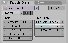 The basic controls for a particle system control the number of particles that
will be omitted (1000 by default), the range of frame numbers over which the
particles will be omitted (1 to 100 by default), the lifetime of each particle
(50 by default), and the amount of randomness in the lifetime (none by default).
Using the defaults, 10 particles will be created in each of the first 100 frames,
and each particle will last for exactly 50 frames before disappearing.
You also get to choose how the particles are emitted from the mesh. They
can be emitted from the vertices, from the faces, or from the volume inside.
(You might want to try changing the distribution from "Jittered" to "Random",
especially when emitting the particles from the volume.)
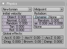 If you change no other settings, the particles will simply stay at the
points where they are created. To give them motion, use the "Physics" controls.
We will stick to "Newtonian" physics for now, but you might want to look into
"Boids". One set of controls sets the initial velocity of the particles.
The "Object" input allows the particles to get some initial velocity from
the motion of the emitter object. If the position of the object is animated
while it is emitting particles, a multiple of the emitter's velocity will be
applied to a particle when it is created. The "Normal" input is useful,
since it gives the particles some initial velocity in the direction perpendicular
to the surface that emits them. And "Random" can be used to add some randomness
to the initial velocity.
The "Global Effects" settings apply forces to the particles as they move. "AccX", "AccY", and "AccZ" apply accelerations in the X, Y and Z directions; these can be used to simulate the effect of wind or gravity. "Drag" adds resistance, that is, a force that acts in the direction opposite to the velocity; this will tend to slow the particles down. "Brown" adds some random changes in velocity, simulating Brownian motion.
Here are a few things to try: Use a Mesh Plane as emitter, set the "Normal" component of initial velocity to 2 and the "Random" component to 1, and set "AccZ" to -2; observe the animation from a side view (Keypad-3). Use a Mesh cube emitter, set "Emit From" to "Volume" and change the distribution from "Jittered" to "Random", and set "Brown" to 2.
It's time to render a particle system! Go to some frame where particles are visible. Use the Camera view (Keypad-0) to make sure that the camera can see them. Render the scene. You should see a whitish ball of light at each particle. This is the default rendering. Note that the emitter object is not rendered.
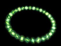 The ball of light is actually
a "halo". Note that the scene doesn't have to be lit to see the halos; they
emit color even in the absence of light.
To change the appearance of the halo, go to the Material buttons (F5)
while the emitter object is selected. Hit the "Halo" button under Render
Pipeline. The color controls under "Material", to the left, will change to
Halo color controls, and the "Shader" controls, to the right, will change to
Halo property controls. (You can actually render any object, not just a
particle system, with a Halo material. You will get a halo at each vertex of
the object. The picture shows a Mesh Circle rendered with
a Halo material.)
You can turn the ball of light that represents the halo into a star by turning on the "Star" option on the right side of the "Shaders" pane. The "Star" input, on the left side of the "Shaders" pane, determines how may points the star will have; it has no effect unless the "Star" option is turned on. Similarly, the "Rings" and "Lines" options add features to the Halo, and the "Rings" and "Lines" inputs determine how many of that feature are added. The color of the lines and rings can be set in the Materials pane. You'll also want to take note of the "Halo Size" input.
As an alternative to halo rendering of the particle system, you can place a copy of any given object at each particle. Just set the "Visualization" to "Object", and enter the name of the object in the "OB" input box. (In the "Physics" pane, try setting the "Angular v" from "None" to "Spin" and setting the associated input to 1.)
Here is a particle system animation that I did some time ago, showing smoke coming out of a smokestack:
Smoke Animation (AVI Jpeg, 951K)
A lattice is a three-dimensional grid. It does not render as an object, but it can influence other objects. In particular, it can be used to deform objects. Lattice deformation is another kind of modeling, and it can also be used for some interesting animations.
To use lattice deformation, first model an object with a basic, non-deformed shape. For the deformation to work well, the shape should have a lot of vertices. If the basic shape does not, then consider subdividing it and/or using a Subsurf modifier. For my example, I used a Mesh Cube, subdivided it twice (in Edit mode with all vertices selected), and added a Subsurf. When you have the basic object, add a lattice to the scene at the same location as the object (using Add / Lattice). Scale the lattice so that it just encloses the basic object. Select the basic object with a right-click, then shift-right-click the lattice. Hit Control-P, and choose "Lattice Deform" from the popup. Now, if you move the vertices of the lattice in edit mode, the object will be deformed. The vertices act like control points for the object.
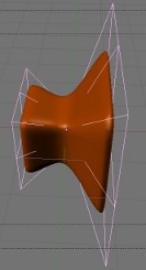 To get better control of the deformation, you will need add points to the
lattice. With the lattice selected, go to the Edit buttons (F9). You
will find a "Lattice" pane where you can set the number of points in
the lattice in the "U", "V", and "W" directions (which are really the X,
Y, and Z directions). In my example, I used U=4 and V=W=3. Use as many
points as you need to get the control that you want. In my example, shown
at the right, I enclosed the cube in a lattice, scaled up the vertices on the
right end of the lattice and scaled down the vertices in the middle of the
lattice. The effect on the cube is shown.
What makes this interesting for animation is that the effect of the lattice on the object depends on the position of the object with respect to the lattice. If you animate the object so that it moves through the lattice, the object will be progressively deformed by the lattice as it moves. Here is a 50-frame animation that I made by moving the cube in my example:
Lattice Deformation Animation (AVI Jpeg, 447K)
Maybe you can imagine using something like this to show a starship going into warp drive?
There are a couple of modifiers that can be added to a mesh to produce animation effects. (Recall that modifiers are added in the "Modifiers" pane of the Edit buttons.)
A "Wave" modifier will produce a wave-like deformation of a mesh, and the wave moves over time as the animation proceeds. You might want to try this on a Mesh Grid that has a lot of points. I suggest that you decrease the speed of the wave, and maybe the height and width as well.
An "Explode" modifier can also be used for animation. I can make a mesh fly into pieces. In order to use it, you must first add a particle system to the mesh. Set up some physics to make the particles move. Also set the "Visualization" of the mesh to "None", and then turn on the "Render Emitter" option. (This is important if you want to see pieces of the mesh flying away.) You probably want to randomize the order in which particles are emitted by the faces of the mesh (although non-random orderings can give interesting results as well). In my example, I set all the particles to be emitted in the first few frames.
After setting up the particle system, add an "Explode" modifier to the mesh. The pieces of the surface will follow the motion of the particles. If you want the exploded pieces of the mesh to disappear after the particles die, turn off the "Dead" option in the Explode modifier. There shouldn't be anything more to it than that! Here is a sample animation of an exploding sphere:
Exploding Sphere Animation (AVI Jpeg, 774K)
We have looked at many ways of deforming and transforming objects, but so far we have done nothing with changing the basic shape of an object by moving its individual vertices. It is not possible in Blender to animate individual vertices with keyframe animation -- there are too many of them. There are, however, some techniques that let you animate the position of individual vertices within an object. One of them, known as "shape keys", is quite general, but rather touchy and hard to use; it is not covered here. A less general technique that is easy to use is known as hooks. A hook is an object that influences a vertex or group of vertices within an object. You can make the vertices move by animating the hook object. Usually, the hook is an Empty object, and therefore not visible in the rendered image.
You can add a hook to a mesh, curve, or surface. Select the object that you want the hook to influence and go into edit mode. Select all the vertices that you want the hook to control. Hit Control-H, and select "Add, to new Empty" from the popup. An Empty object appears in the middle of the selected set of vertices, and those vertices are "hooked" to the Empty.
By default, the hooked vertices are locked to the Empty. If you transform the Empty by dragging, scaling, or rotating, the hooked vertices are dragged along -- and if you transform the object, only the vertices that are not hooked to the Empty will move!
You can change this default behavior, to make the influence of the hook decrease as the distance from the hook increases. To do this, select the object that the hook influences. Go to the "Modifiers" pane in the Edit buttons. You will see that the hook is listed as a modifier. One of the properties of the modifier is "Falloff". The default value, 0, means that the influence of the hook does not decrease at all with distance. When set to a positive value, the Falloff gives the distance from the hook where the influence ends. The influence falls off proportionately between zero distance and the falloff distance.
Note that you can attach as many hooks as you want to an object. When several hooks influence the same vertex, the degree to which each one affects the vertex is determined by the relative "force" of each of the hooks. This force can be set in the same Modifier pane where the Falloff setting is found.
To make the following animation, I used a 7-vertex cylinder. In edit mode, I selected the 7 vertices on the top of the cylinder, and I added a hook to control those vertices. I then animated the Empty hook object using basic keyframe animation, to make it move up and down while rotating, dragging the vertices along with it. Since I didn't set a falloff value for the hook, the 7 controlled vertices move along with the hook as a rigid object:
Hook Animation (AVI Jpeg, 672K)