CS 424: Computer Graphics, Spring 2012
Lab 7: Blender Animation
For this lab, you will produce one or more animations using Blender, subject to certain requirements. The only real requirement is that you should make use of at least one example of each of the following four animation techniques, which are discussed on the rest of this page:
- Keyframe animation
- Path animation
- Particle system
- Another technique such as lattice deformation, an animation modifier, or vertex hooking.
You could do this all in one rendered animation, but you will probably find it easier to make several rendered animations -- possibly of the same scene using different camera angles or camera animations.
I suggest rendering the animation(s) in AVI JPEG format, using a rather small frame size -- maybe 400-by-300. You should put links to the animations on your web site. It would be a good idea to post stills from the animations on your web page. It would be a very good idea to explain where in the animation you use the various animation techniques. You should save the .blend file(s) that you use to make the animations.
My idea was that you would start from the scene that you created for Lab 5 and add animation to that scene. (However, you are not actually required to do that.) You might make the flying objects move or the sky change colors with keyframe animation; use path animation on a camera; add a particle system for rain, airplane exhaust, fireflies, or fairy dust; and make a tree explode with an explode modifier, water ripple with a wave modifier, or a snowman expand in size with a lattice deformation. You might do all the animations in one scene, or you might make several copies of the scene and do different animations in each copy.
Don't forget to save a copy of your Lab 5 .blend file before you start modifying it! I expect to see your web page for Lab 5 in your web portfolio by Friday afternoon. Your web page should include the four images that are required for Lab 5.
More Controls
There are a few more controls that you will need to know about. Look for the "Render", "World", and "Scene" buttons in the properties pane along the right edge of the Blender window:"
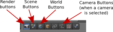
Here are a few things you can do with the controls revealed by these buttons:
In the World controls, near the bottom, you can turn on and configure Mist and Stars. At the top, you can control the background of the rendered image. Turn on "Blend" and set the "Horizon Color" and "Zenith" to get a color gradient from the bottom to the top of the sky. Also, you can add a texture to the sky. Click from the World controls to the Texture controls; make sure that you are editing the world texture. Add a texture and configure it. To see the most effect, make sure that "Horizon" is checked under "Influence."
In the Scene controls, you can select which camera you want to use to render the scene and to view the scene in the camera perspective. (You can have more than one camera in a scene.) You can also change the active camera by selecting the camera in the 3D view and hitting CONTROL-KEYPAD-0 Further down in the Scene pane, you can turn off Gravity entirely, or change the amount or direction of the gravitational force.
The Render controls are especially important for animation. At the top, you will find buttons that you can use to render an individual image or an animation. (These duplicate the F12 key and the render commands in the menu bar.) The "Resolution" controls the size of the image that will be produced. You can specify the X and Y dimensions and a percentage; the stated dimensions are multiplied by the percentage to get the actual image size (presumably to make it easy to make small size test runs). The "Frame Range" duplicates the animation start and end frames from the timeline. Note that the "Frame Step" lets you render just a subset of the frames. For example, set it to 2 to render every other frame.
You can turn off some features during rendering if you want to speed things up. Anti-aliasing, for example, is something that should always be on to produce a good quality image, but it does take extra time to compute. (You might increase the Anti-Aliasing setting to "16" when you want the best quality.) Similarly, you can turn off shadows, textures, etc, under "Shading."
Under "Output" near the bottom of the Render settings, you can select a directory and base file name for animation output. Note that the default is to send the output to the /tmp directory. (You can change the default directory for render output in the user preferences.) You can also set the format of the output. Note that if an image format, such as PNG, is selected when rendering an animation, then each frame of the animation will be rendered as a separate image file. This is something that is often done to allow further processing, but you probably want to use something like AVI JPEG or H.264.
(Finally, I'll note that in the Camera controls, which are available when a camera is the selected object, you'll find the "Clipping range" for the camera. This is the range of distances from the camera that is visible in the scene. If an object is farther from the camera than the camera's "End" clipping value, then the object is not seen by the camera. If you have a problem with faraway objects disappearing, check the camera clipping range.)
Keyframe Animation
The most basic type of animation is keyframe animation, which was covered in the Lab 5 warmup and was demonstrated in class. You can insert keyframes for the location, rotation, and scaling of an object -- including lights and cameras. You can also have keyframes for other properties, such as colors, transparency, and texture transforms.
As you get into keyframe animation, you might find that you need more control. The interpolation between keyframes is controlled by functions called F-curves. You can see the F-curves and edit them in the Graph Editor pane, which is not part of the Default screen. It is, however, part of the Animation screen. To get to that screen, choose "Animation" from the Screen menu at the top of the Blender window. (Click the icon next to the word "Default".) The Graph editor will be in the lower left. It's too small to be useful; increase its size by dragging the upper border. Here is the Graph editor showing F-curves for an animated cone:
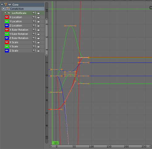
Each curve controls one component of the animation. The curves are (by default) Bezier curves with handles that you can select and edit in the usual way. The little "+" sign near the upper right can be clicked to reveal another pane of controls, including modifiers that can be applied to the curves. I won't say more about all this here, but you should know that the curve-editing capability is there if you ever need it.
Parenting and Tracking
Recall that you can "parent" one object to another: Right-click the child object to select it, then shift-right-click the parent object. Hit CONTROL-P and select "Object" from the pop-up menu. Note that you can clear a parent relationship by selecting the child object and hitting ALT-P. Later, you'll see that certain types of objects (curves and latices) support different kinds of parenting relationships for special effects.
Similar to parenting is tracking. When one object tracks another, the rotation of the first object is always set so that it faces the object that it is tracking. To set up a tracking relation, shift-click the object that you want to do the tracking, then right-shift-click the object that you want it to track. Hit CONTROL-T. You will have a choice of three different types of tracking. The first, "Damped Track Constraint" seems to work well in general, but "Track To Constraint" seems to work better when it's a camera that's doing the tracking. Tracking is in fact a constraint, and after you set it up you will find it listed in Constraint controls for the tracking object. In those controls, you can set the axis of the tracking object that will point towards the object that is being tracked.
Tracking works especially well for cameras and spotlights. You can make them track moving objects, so that the camera or light is always pointed at the object.
Path Animation
Path animation can be used to move an object along a path. A path in Blender is a kind of curve (actually just a NURBS curve with certain properties). To add a path to a scene, use Add / Curve / Path (or use Add / Curve / Nurbs Circle for a path that is already closed). Recall that you can extend a path by going into edit mode, selecting one of the endpoints, and using control-left-click to add points. You can add points in the middle by selecting a pair of consecutive control points and hitting "Subdivide" in the pane on the left. You can close the path by hitting ALT-C key while in edit mode. A path is not constrained to lie in a plane, but I suggest that you first create a 2D path, then move some control points around in edit mode to get a 3D curve
To make an object follow the path, select the object by right-clicking it, then shift-right-click the path. Hit Control-P, and choose "Follow Path" from the popup. The object will be joined to the path by a dotted line. Note that the object doesn't jump to the path, but you will probably want to move it onto the path. (Suggestion: Go to frame 1; select the path; go into edit mode and select the starting vertex of the path; use Shift-S / Cursor-to-Selection to move the cursor to the start of the path; leave edit mode; select the object; and use Shift-S / Selection-to-Cursor. This will position the object exactly on the path at frame 1. You might want to set the object's rotation numerically, in the Object controls, to get it exactly right.)
By default, the object -- actually, the point at which the object is attached to the path -- moves along the path from beginning to end between frame 1 and frame 100. You can see this by changing the frame number. You can change the path length in the path's Object Data controls, under "Path Animation." Generally, you will want to increase the number of frames quite a bit. Remember that 100 frames is only about 4 seconds!
Note that path animation is not just for objects! You can move a Camera or Lamp along a path. You can combine path animation with tracking in several ways. For example, set up a Camera to track an Empty and move the Empty along a path to tell the Camera where to point. Or do the same thing with a spotlight. Or have a Camera track some object, and set the Camera to follow a path at the same time, to make the Camera move around while looking all the time at the same object.
Here is an animation that I made some years ago that uses path animation to move a camera around a ball bouncing on a pedestal:
Particle Systems
A particle system is a bunch of free-floating vertices that move under the influence of forces or other controls. Particle systems can represent everything from a cloud of smoke to a flock of birds. So-called "Hair" particle systems, in which the entire path of each particle is rendered at once, can be used to simulate things like hair and grass. Blender particle systems are very complicated, and I will only mention a few of the options here.
In Blender, particles are emitted by mesh objects only. To turn a mesh object into a particle-emitter, select the object, click the Particle System button -- shown in the following image -- in the properties pane. You should see a "+" button in the control area, next to an empty rectangle. Click the "+" button and a large number of new controls will appear. These are the controls that you use to configure the particle system. Here is a guide to some of them:
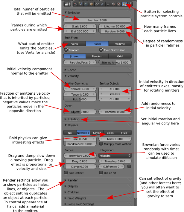
Particles are shown in the 3D window, by default, as dots (this can be changed in the settings). The calculations that are required to implement the particle system are computed frame-by-frame and cached. Drag the green line in the timeline to sweep through the frames and see how the particles move. To make sure that they reflect all the changes that you make to the settings, you might have to start back in frame 1.
By default, the initial velocity of the particles is 1 and is in the direction of the normal vector at the point that emits them. They are subject to a gravitational force that makes them accelerate in the negative y-direction. There are controls to change the initial velocity and to turn off gravity. If you turn off initial velocity and gravity, the particle stays at the point where it is created -- which might be OK if the emitter is moving.
Particles can also be affected by forces that you add to the scene, using the "Force Field" sub-menu of the add menu.
 When you render a particle system, with the default render settings,
you should see a whitish ball of light at
each particle. The ball of light is
a "halo". Note that the scene doesn't have to be lit to see the halos; they
emit color even in the absence of light.
To change the appearance of the halo, go to the Material controls
while the emitter object is selected. Add a material if you have not
done so already, and change the material type from "Surface" to "Halo".
You will see a new set of halo property controls.
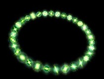
(You can actually render any mesh object, not just a
particle system, with a Halo material. You will get a halo at each vertex of
the object. The picture shows a Mesh Circle rendered with
a Halo material.)
When you render a particle system, with the default render settings,
you should see a whitish ball of light at
each particle. The ball of light is
a "halo". Note that the scene doesn't have to be lit to see the halos; they
emit color even in the absence of light.
To change the appearance of the halo, go to the Material controls
while the emitter object is selected. Add a material if you have not
done so already, and change the material type from "Surface" to "Halo".
You will see a new set of halo property controls.
(You can actually render any mesh object, not just a
particle system, with a Halo material. You will get a halo at each vertex of
the object. The picture shows a Mesh Circle rendered with
a Halo material.)
You can turn the ball of light that represents the halo into a star by turning on the "Star Tips" option in the Halo controls. You can set the number of points of the stars -- to 5, for example -- by changing the number in the "Star Tips" box. Similarly, the "Rings" and "Lines" options add features to the Halo, and the "Rings" and "Lines" inputs determine how many of that feature are added. The color of the lines and rings can be set by clicking the color patch just below the corresponding checkbox.
You might also want to change the "Size" property of the halo material.
As an alternative to halo rendering of the particle system, you can place a copy of any given object at each particle. In the Particle controls, set the "Rendering" to "Object", and select a "Dupli Object". Set the size as well, since the default size is probably much too small. Adding rotation to the particle system might be a good idea if you are duplicating an object and want the duplicates to spin.
Here is a particle system animation that I did some time ago, showing smoke coming out of a smokestack:
Lattice Deformation
A lattice is a three-dimensional grid. It does not render as an object, but it can influence other objects. In particular, it can be used to deform objects. Lattice deformation is another kind of modeling, and it can also be used for some interesting animations.
To use lattice deformation, first model an object with a basic, non-deformed shape. For the deformation to work well, the shape should have a lot of vertices. If the basic shape does not, then consider subdividing it and/or using a Subdivision Surface modifier. For my example, I used a Mesh Cube, subdivided it twice (in Edit mode with all vertices selected), and added a subsurface modifier. When you have the basic object, add a lattice to the scene at the same location as the object (using Add / Lattice). Scale the lattice so that it just encloses the basic object. Select the basic object with a right-click, then shift-right-click the lattice. Hit Control-P, and choose "Lattice Deform" from the popup. Now, if you move the vertices of the lattice when the lattice is selected and in edit mode, then the object will be deformed. The vertices act like control points for the object.
 To get better control of the deformation, you will need add points to the
lattice. With the lattice selected, go to the object data controls for
the lattice.
To get better control of the deformation, you will need add points to the
lattice. With the lattice selected, go to the object data controls for
the lattice.  (Click the Object Data button in the properties pane;
the object data button for latices is shown at the left.) You
will find a control where you can set the number of points in
the lattice in the "U", "V", and "W" directions (which are really the X,
Y, and Z directions). In my example, I used U=4 and V=W=3. Use as many
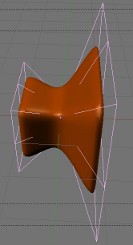
points as you need to get the control that you want. In my example, shown
at the right, I enclosed the cube in a lattice, scaled up the vertices on the
right end of the lattice and scaled down the vertices in the middle of the
lattice. The effect on the cube is shown.
(Click the Object Data button in the properties pane;
the object data button for latices is shown at the left.) You
will find a control where you can set the number of points in
the lattice in the "U", "V", and "W" directions (which are really the X,
Y, and Z directions). In my example, I used U=4 and V=W=3. Use as many
points as you need to get the control that you want. In my example, shown
at the right, I enclosed the cube in a lattice, scaled up the vertices on the
right end of the lattice and scaled down the vertices in the middle of the
lattice. The effect on the cube is shown.
What makes this interesting for animation is that the effect of the lattice on the object depends on the position of the object with respect to the lattice. If you animate the object so that it moves through the lattice, the object will be progressively deformed by the lattice as it moves. (Alternatively, you could leave the object in place and animate the lattice.) Here is a 50-frame animation that I made by moving the cube in my example:
Lattice Deformation Animation (AVI Jpeg, 447K)
Maybe you can imagine using something like this to show a starship going into warp drive?
Animation Modifiers
There are a couple of modifiers that can be added to a mesh to produce animation effects. (Recall that modifiers are added in the "Modifiers" controls in the properties pane, selected with the "monkey wrench" icon.)
A "Wave" modifier will produce a wave-like deformation of a mesh, and the wave moves over time as the animation proceeds. You might want to try this on a Mesh Grid that has a lot of points. I suggest that you decrease the speed of the wave, and maybe the height and width as well.
An "Explode" modifier can also be used for animation. I can make a mesh fly into pieces. Use a mesh with a lot of faces. In order for "Explode" to work, you must first add a particle system to the mesh. Set up some physics to make the particles move. The number of particles gives the number of pieces into which the mesh will break (with the number of faces of the mesh being the maximum number of particles that can be used). Under "Render", choose "None", but make sure that the "Emitter" option under "Render" is turned on. (This is important if you want to see pieces of the mesh flying away.) You might want to add some rotation to the particles. In my example, I set all the particles to be emitted in the first few frames.
After setting up the particle system, add an "Explode" modifier to the mesh. (You will see that the particle system is also listed as a modifier.) The pieces of the surface will follow the motion of the particles. If you want the exploded pieces of the mesh to disappear after the particles die, turn off the "Dead" option in the Explode modifier; leave the "Alive" option on, or you won't see the moving pieces; leave the "Unborn" option on, or you won't see the piece on the original surface before the corresponding particle is emitted. Here is a sample animation of an exploding sphere:
Hook Yourself Some Vertices
We have looked at many ways of deforming and transforming objects, but so far we have done nothing with changing the basic shape of an object by moving its individual vertices. It is not possible in Blender to animate individual vertices with keyframe animation -- there are too many of them. There are, however, some techniques that let you animate the position of individual vertices within an object, including a very general one that I won't cover here. A less general technique that is easy to use is known as hooks. A hook is an object that influences a vertex or group of vertices within an object. You can make the vertices move by animating the hook object. Usually, the hook is an Empty object, and therefore not visible in the rendered image.
You can add a hook to a mesh, curve, or surface. Select the object that you want the hook to influence and go into edit mode. Select all the vertices that you want the hook to control. Hit Control-H, and select "Hook to new Empty" from the popup. An Empty object appears in the middle of the selected set of vertices, and those vertices are "hooked" to the Empty.
By default, the hooked vertices are locked to the Empty. If you transform the Empty by dragging, scaling, or rotating, the hooked vertices are dragged along -- and if you transform the object, only the vertices that are not hooked to the Empty will move!
You can change this default behavior, to make the influence of the hook decrease as the distance from the hook increases. To do this, select the object that the hook influences. Go to the "Modifiers" controls in the properties pane. You will see that the hook is listed as a modifier. One of the properties of the modifier is "Falloff". The default value, 0, means that the influence of the hook does not decrease at all with distance. When set to a positive value, the Falloff gives the distance from the hook where the influence ends. The influence falls off proportionately between zero distance and the falloff distance.
To make the following animation, I used a 7-vertex cylinder. In edit mode, I selected the 7 vertices on the top of the cylinder, and I added a hook to control those vertices. I then animated the Empty hook object using basic keyframe animation, to make it move up and down while rotating, dragging the vertices along with it. Since I didn't set a falloff value for the hook, the 7 controlled vertices move along with the hook as a rigid object: