Section 4.1
Introduction to Lighting
Lighting is one of the most important considerations for realistic 3D graphics. The goal is to simulate light sources and the way that the light that they emit interacts with objects in the scene. Lighting calculations are disabled by default in OpenGL. This means that when OpenGL applies color to a vertex, it simply uses the current color value as set by the one of the functions glColor*. In order to get OpenGL to do lighting calculations, you need to enable lighting by calling glEnable(GL_LIGHTING). If that's all you do, you will find that your objects are all completely black. If you want to see them, you have to turn on some lights.
The properties of a surface that determine how it interacts light are referred to as the material of the surface. A surface can have several different material properties. Before we study the OpenGL API for light and material, there are a few general ideas about light and material properties that you need to understand. Those ideas are introduced in this section. We postpone discussion of how lighting is actually done in OpenGL 1.1 until the next section.
4.1.1 Light and Material
When light strikes a surface, some of it will be reflected. Exactly how it reflects depends in a complicated way on the nature of the surface, what I am calling the material properties of the surface. In OpenGL 1.1, the complexity is approximated—very crudely—by two general types of reflection, specular reflection and diffuse reflection. These two types of reflection are important in other 3D graphics systems as well. (But see Section 8.2 for a more modern view of materials.)
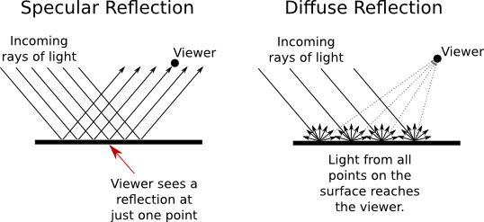
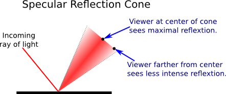
In perfect specular ("mirror-like") reflection, an incoming ray of light is reflected from the surface intact. The reflected ray makes the same angle with the surface as the incoming ray. A viewer can see the reflected ray only if the viewer is in exactly the right position, somewhere along the path of the reflected ray. Even if the entire surface is illuminated by the light source, the viewer will only see the reflection of the light source at those points on the surface where the geometry is right. Such reflections are referred to as specular highlights. In practice, we think of a ray of light as being reflected not as a single perfect ray, but as a cone of light, which can be more or less narrow.
Specular reflection from a very shiny surface produces very narrow cones of reflected light; specular highlights on such a material are small and sharp. A duller surface will produce wider cones of reflected light and bigger, fuzzier specular highlights. In OpenGL, the material property that determines the size and sharpness of specular highlights is called shininess. Shininess in OpenGL is a number in the range 0 to 128. As the number increases, specular highlights get smaller. This image shows eight spheres that differ only in the value of the shininess material property:
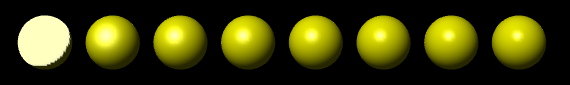
For the sphere on the left, the shininess is 0, which leads to an ugly specular "highlight" that almost covers an entire hemisphere. Going from left to right, the shininess increases by 16 from one sphere to the next.
In pure diffuse reflection, an incoming ray of light is scattered in all directions equally. A viewer would see reflected light from all points on the surface. If the incoming light arrives in parallel rays that evenly illuminate the surface, then the surface would appear to the viewer to be evenly illuminated. (If different rays strike the surface at different angles, as they would if they come from a nearby lamp or if the surface is curved, then the amount of illumination at a point depends on the angle at which the ray hits the surface at that point, but not on the angle of the line from that point to the user.)
When light strikes a surface, some of the light can be absorbed, some can be reflected diffusely, and some can be reflected specularly. The amount of reflection can be different for different wavelengths. The degree to which a material reflects light of various wavelengths is what constitutes the color of the material. We now see that a material can have two different colors—a diffuse color that tells how the material reflects light diffusely, and a specular color that tells how it reflects light specularly. The diffuse color is the basic color of the object. The specular color determines the color of specular highlights. The diffuse and specular colors can be the same; for example, this is often true for metallic surfaces. Or they can be different; for example, a plastic surface will often have white specular highlights no matter what the diffuse color.
here is a demo that lets you experiment with the material properties that we have discussed so far. Read the help text in the demo for more information.
OpenGL goes even further. In fact, there are two more colors associated with a material. The third color is the ambient color of the material, which tells how the surface reflects ambient light. Ambient light refers to a general level of illumination that does not come directly from a light source. It consists of light that has been reflected and re-reflected so many times that it is no longer coming from any particular direction. Ambient light is why shadows are not absolutely black. In fact, ambient light is only a crude approximation for the reality of multiply reflected light, but it is better than ignoring multiple reflections entirely. The ambient color of a material determines how it will reflect various wavelengths of ambient light. Ambient color is generally set to be the same as the diffuse color.
The fourth color associated with a material is an emission color, which is not really a color in the same sense as the first three color properties. That is, it has nothing to do with how the surface reflects light. The emission color is color that does not come from any external source, and therefore seems to be emitted by the material itself. This does not mean that the object is giving off light that will illuminate other objects, but it does mean that the object can be seen even if there is no source of light (not even ambient light). In the presence of light, the object will be brighter than can be accounted for by the light that illuminates it, and in that sense it appears to glow. The emission color is usually black; that is, the object has no emission at all.
Each of the four material color properties is specified in terms of three numbers giving the RGB (red, green, and blue) components of the color. Real light can contain an infinite number of different wavelengths. An RGB color is made up of just three components, but the nature of human color vision makes this a pretty good approximation for most purposes. (See Subsection 2.1.4.) Material colors can also have alpha components, but the only alpha component that is ever used in OpenGL is the one for the diffuse material color.
In the case of the red, blue, and green components of the ambient, diffuse, or specular color, the term "color" really means reflectivity. That is, the red component of a color gives the proportion of red light hitting the surface that is reflected by that surface, and similarly for green and blue. There are three different types of reflective color because there are three different types of light in OpenGL, and a material can have a different reflectivity for each type of light.
4.1.2 Light Properties
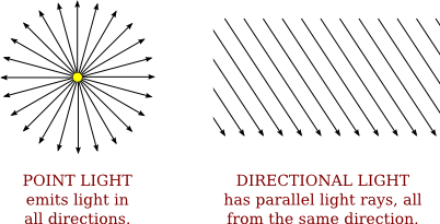
Leaving aside ambient light, the light in an environment comes from a light source such as a lamp or the sun. In fact, a lamp and the sun are examples of two essentially different kinds of light source: a point light and a directional light. A point light source is located at a point in 3D space, and it emits light in all directions from that point. For a directional light, all the light comes from the same direction, so that the rays of light are parallel. The sun is considered to be a directional light source since it is so far away that light rays from the sun are essentially parallel when they get to the Earth .
A light can have color. In fact, in OpenGL, each light source has three colors: an ambient color, a diffuse color, and a specular color. Just as the color of a material is more properly referred to as reflectivity, color of a light is more properly referred to as intensity or energy. More exactly, color refers to how the light's energy is distributed among different wavelengths. Real light can contain an infinite number of different wavelengths; when the wavelengths are separated, you get a spectrum or rainbow containing a continuum of colors. Light as it is usually modeled on a computer contains only the three basic colors, red, green, and blue. So, just like material color, light color is specified by giving three numbers representing the red, green, and blue intensities of the light.
The diffuse intensity of a light is the aspect of the light that interacts with diffuse material color, and the specular intensity of a light is what interacts with specular material color. It is common for the diffuse and specular light intensities to be the same.
The ambient intensity of a light works a little differently. Recall that ambient light is light that is not directly traceable to any light source. Still, it has to come from somewhere and we can imagine that turning on a light should increase the general level of ambient light in the environment. The ambient intensity of a light in OpenGL is added to the general level of ambient light. (There can also be global ambient light, which is not associated with any of the light sources in the scene.) Ambient light interacts with the ambient color of a material, and this interaction has no dependence on the position of the light sources or viewer. So, a light doesn't have to shine on an object for the object's ambient color to be affected by the light source; the light source just has to be turned on.
I should emphasize again that this is all just an approximation, and in this case not one that has a basis in the physics of the real world. Real light sources do not have separate ambient, diffuse, and specular colors, and many computer graphics systems model light sources using just one color.
4.1.3 Normal Vectors
The visual effect of a light shining on a surface depends on the properties of the surface and of the light. But it also depends to a great extent on the angle at which the light strikes the surface. The angle is essential to specular reflection and also affects diffuse reflection. That's why a curved, lit surface looks different at different points, even if its surface is a uniform color. To calculate this angle, OpenGL needs to know the direction in which the surface is facing. That direction is specified by a vector that is perpendicular to the surface. Another word for "perpendicular" is "normal," and a non-zero vector that is perpendicular to a surface at a given point is called a normal vector to that surface. When used in lighting calculations, a normal vector must have length equal to one. A normal vector of length one is called a unit normal. For proper lighting calculations in OpenGL, a unit normal must be specified for each vertex. However, given any normal vector, it is possible to calculate a unit normal from it by dividing the vector by its length. (See Section 3.5 for a discussion of vectors and their lengths.)
Since a surface can be curved, it can face different directions at different points. So, a normal vector is associated with a particular point on a surface. In OpenGL, normal vectors are actually assigned only to the vertices of a primitive. The normal vectors at the vertices of a primitive are used to do lighting calculations for the entire primitive.
Note in particular that you can assign different normal vectors at each vertex of a polygon. Now, you might be asking yourself, "Don't all the normal vectors to a polygon point in the same direction?" After all, a polygon is flat; the perpendicular direction to the polygon doesn't change from point to point. This is true, and if your objective is to display a polyhedral object whose sides are flat polygons, then in fact, all the normals of each of those polygons should point in the same direction. On the other hand, polyhedra are often used to approximate curved surfaces such as spheres. If your real objective is to make something that looks like a curved surface, then you want to use normal vectors that are perpendicular to the actual surface, not to the polyhedron that approximates it. Take a look at this example:
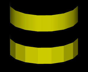
The two objects in this picture are made up of bands of rectangles. The two objects have exactly the same geometry, yet they look quite different. This is because different normal vectors are used in each case. For the top object, the band of rectangles is supposed to approximate a smooth surface. The vertices of the rectangles are points on that surface, and I really didn't want to see the rectangles at all—I wanted to see the curved surface, or at least a good approximation. So for the top object, when I specified the normal vector at each of the vertices, I used a vector that is perpendicular to the surface rather than one perpendicular to the rectangle. For the object on the bottom, on the other hand, I was thinking of an object that really is a band of rectangles, and I used normal vectors that were actually perpendicular to the rectangles. Here's a two-dimensional illustration that shows the normal vectors that were used for the two pictures:
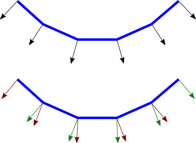
The thick blue lines represent the rectangles, as seen edge-on from above. The arrows represent the normal vectors. Each rectangle has two normals, one at each endpoint. Each vertex is part of two rectangles, and so two normal vectors are specified at each vertex.
In the bottom half of the illustration, two rectangles that meet at a point have different normal vectors at that point. The normal vectors for a rectangle are actually perpendicular to the rectangle. There is an abrupt change in direction as you move from one rectangle to the next, so where one rectangle meets the next, the normal vectors to the two rectangles are different. The visual effect on the rendered image is an abrupt change in shading that is perceived as a corner or edge between the two rectangles.
In the top half, on the other hand, the vectors are perpendicular to a curved surface that passes through the endpoints of the rectangles. When two rectangles share a vertex, they also share the same normal at that vertex. Visually, this eliminates the abrupt change in shading, resulting in something that looks more like a smoothly curving surface.
The two ways of assigning normal vectors are called flat shading and smooth shading. Flat shading makes a surface look like it is made of flat sides or facets. Smooth shading makes it look more like a smooth surface. This demo will help you to understand these concepts. It shows a polygonal mesh being used to approximate a sphere, with your choice of smooth or flat shading. Use the sliders to control the number of polygons in the mesh.
The upshot of all this is that you get to make up whatever normal vectors suit your purpose. A normal vector at a vertex is whatever you say it is, and it does not have to be literally perpendicular to the polygon. The normal vector that you choose should depend on the object that you are trying to model.
There is one other issue in choosing normal vectors: There are always two possible unit normal vectors at a point on a surface, pointing in opposite directions. A polygon in 3D has two faces, facing in opposite directions. OpenGL considers one of these to be the front face and the other to be the back face. OpenGL tells them apart by the order in which the vertices are specified. (See Subsection 3.4.1.) The default rule is that the order of the vertices is counterclockwise when looking at the front face and is clockwise when looking at the back face. When the polygon is drawn on the screen, this rule lets OpenGL tell whether it is the front face or the back face that is being shown. When specifying a normal vector for the polygon, the vector should point out of the front face of the polygon. This is another example of the right-hand rule. If you curl the fingers of your right hand in the direction in which the vertices of the polygon were specified, then the normal vector should point in the direction of your thumb. Note that when you are looking at the front face of a polygon, the normal vector should be pointing towards you. If you are looking at the back face, the normal vector should be pointing away from you.
It can be a difficult problem to come up with the correct normal vectors for an object. Complex geometric models often come with the necessary normal vectors included. This is true, for example, for the solid shapes drawn by the GLUT library.
4.1.4 The OpenGL 1.1 Lighting Equation
What does it actually mean to say that OpenGL performs "lighting calculations"? The goal of the calculation is to produce a color, (r,g,b,a), for a point on a surface. In OpenGL 1.1, lighting calculations are actually done only at the vertices of a primitive. After the color of each vertex has been computed, colors for interior points of the primitive are obtained by interpolating the vertex colors.
The alpha component of the vertex color, a, is easy: It's simply the alpha component of the diffuse material color at that vertex. The calculation of r, g, and b is fairly complex and rather mathematical, and you don't necessarily need to understand it. But here is a short description of how it's done...
Ignoring alpha components, let's assume that the ambient, diffuse, specular, and emission colors of the material have RGB components (mar,mag,mab), (mdr,mdg,mdb), (msr,msg,msb), and (mer,meg,meb), respectively. Suppose that the global ambient intensity, which represents ambient light that is not associated with any light source in the environment, is (gar,gag,gab). There can be several point and directional light sources, which we refer to as light number 0, light number 1, light number 2, and so on. With this setup, the red component of the vertex color will be:
r = mer + gar*mar + I0,r + I1,r + I2,r + ...
where I0,r is the red component of the contribution to the color that comes from light number 0; I1,r is the contribution from light number 1; and so on. A similar equation holds for the green and blue components of the color. This equation says that the emission color, mer, is simply added to any other contributions to the color. And the contribution of global ambient light is obtained by multiplying the global ambient intensity, gar, by the material ambient color, mar. This is the mathematical way of saying that the material ambient color is the fraction of the ambient light that is reflected by the surface.
The terms I0,r, I1,r, and so on, represent contributions to the final color from the various light sources in the environment. The contributions from the light sources are complicated. Consider just one of the light sources. Note, first of all, that if a light source is disabled (that is, if it is turned off), then the contribution from that light source is zero. For an enabled light source, we have to look at the geometry as well as the colors:
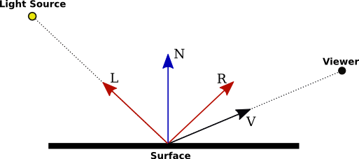
In this illustration, N is the normal vector at the point whose color we want to compute. L is a vector that points back along the direction from which the light arrives at the surface. V is a vector that points in the direction of the viewer. And R is the direction of the reflected ray, that is, the direction in which a light ray from the source would be reflected specularly when it strikes the surface at the point in question. The angle between N and L is the same as the angle between N and R; this is a basic fact about the physics of light. All of the vectors are unit vectors, with length 1. Recall that for unit vectors A and B, the inner product A · B is equal to the cosine of the angle between the two vectors. Inner products occur at several points in the lighting equation, as the way of accounting for the angles between various vectors.
Now, let's say that the light has ambient, diffuse, and specular color components (lar,lag,lab), (ldr,ldg,ldb), and (lsr,lsg,lsb). Also, let mh be the value of the shininess property of the material. Then, assuming that the light is enabled, the contribution of this light source to the red component of the vertex color can be computed as
Ir = lar*mar + f*( ldr*mdr*(L·N) + lsr*msr*max(0,V·R)mh )
with similar equations for the green and blue components. The first term, lar*mar accounts for the contribution of the ambient light from this light source to the color of the surface. This term is added to the color whether or not the surface is facing the light.
The value of f is 0 if the surface is facing away from the light and is 1 if the surface faces the light; that is, it accounts for the fact that the light only illuminates one side of the surface. To test whether f is 0 or 1, we can check whether L·N is less than 0. This dot product is the cosine of the angle between L and N; it is less than 0 when the angle is greater than 90 degrees, which would mean that the normal vector is on the opposite side of the surface from the light. When f is zero, there is no diffuse or specular contribution from the light to the color of the vertex.
The diffuse component of the color, before adjustment by f, is given by ldr*mdr*(L·N). This represents the diffuse intensity of the light times the diffuse reflectivity of the material, multiplied by the cosine of the angle between L and N. The angle is involved because for a larger angle, the same amount of energy from the light is spread out over a greater area:
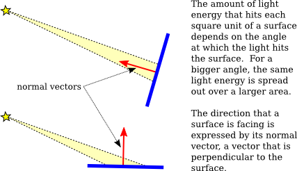
As the angle increases from 0 to 90 degrees, the cosine of the angle decreases from 1 to 0, so the larger the angle, the smaller the value of ldr*mdr*(L·N) and the smaller the contribution of diffuse illumination to the color.
For the specular component, recall that a light ray is reflected specularly as a cone of light. The reflection vector, R, is at the center of the cone. The closer the viewer is to the center of the cone, the more intense the specular reflection. The distance of the viewer from the center of the cone depends on the angle between V and R, which appears in the equation as the dot product V·R. Mathematically, the specular contribution to the color is given by lsr*msr*max(0,V·R)mh. Taking the maximum of 0 and V·R ensures that the specular contribution is zero if the angle between V and R is greater than 90 degrees. Assuming that is not the case, max(0,V·R) is equal to V·R. Note that this dot product is raised to the exponent mh, which is the material's shininess property. When mh is 0, (V·R)mh is 1, and there is no dependence on the angle; in that case, the result is the sort of huge and undesirable specular highlight that we have seen for shininess equal to zero. For positive values of shininess, the specular contribution is maximal when the angle between V and R is zero, and it decreases as the angle increases. The larger the shininess value, the faster the rate of decrease. The result is that larger shininess values give smaller, sharper specular highlights.
Remember that the same calculation is repeated for every enabled light and that the results are combined to give the final vertex color. It's easy, especially when using several lights, to end up with color components larger than one. In the end, before the color is used to color a pixel on the screen, the color components must be clamped to the range zero to one. Values greater than one are replaced by one. This makes it easy to produce ugly pictures in which large areas are a uniform white because all the color values in those areas exceeded one. All the information that was supposed to be conveyed by the lighting has been lost. The effect is similar to an over-exposed photograph. It can take some work to find appropriate lighting levels to avoid this kind of over-exposure.
(My discussion of lighting in this section leaves out some factors. The equation as presented doesn't take into account the fact that the effect of a point light can depend on the distance to the light, and it doesn't take into account spotlights, which emit just a cone of light. Both of these can configured in OpenGL 1.1, but this book does not cover how to do that. There are also many aspects of light that are not captured by the simple model used in OpenGL. One of the most obvious omissions is shadows: Objects don't block light! Light shines right through them. We will encounter some extensions to the model in later chapters when we discuss other graphics systems.)