Section 7.5
WebGL Extensions
WebGL is designed to run on a wide variety of devices, including mobile devices that have relatively limited graphical capabilities. Because of this, only a minimal set of features is required of all WebGL implementations. However, WebGL has a mechanism for activating additional, optional features. The optional features are defined in WebGL extensions. A web page that requires a WebGL extension is not guaranteed to work in every implementation of WebGL. However, in many cases, it is fairly easy to write a page that can work with or without the extension, though perhaps with some missing feature when the extension is not available. There are several dozen extensions whose definitions have been standardized. These standard extensions are documented at https://www.khronos.org/registry/webgl/extensions/.
Standard OpenGL also has an extension mechanism. Historically, many features from extensions in one version of OpenGL have become required features in later versions. The same is true for WebGL extensions: Some of the WebGL 1.0 extensions have been incorporated as required features in WebGL 2.0.
This section covers the WebGL extension mechanism, and it discusses a few of the standard extensions.
7.5.1 Anisotropic Filtering
We start with a simple extension that can improve the appearance of textures in some scenes. The standard filtering methods for sampling an image texture give poor results when the texture is viewed at an oblique angle. In that case, a pixel on the surface corresponds to a trapezoidal region in the texture, and the standard minification and magnification filter rules such as gl.LINEAR don't handle that case very well. (Filtering was covered in Subsection 4.3.2.) A better result can be obtained, at the cost of additional computation, using something called anisotropic filtering, which samples the texture taking the trapezoidal shape into account. Many GPUs can do anisotropic filtering. It is not a required feature in WebGL implementations, but it is commonly available as an extension. The anisotropic filtering extension can be used with both WebGL 1.0 and WebGL 2.0, in the same way.
The sample program webgl/anisotropic-filtering.html shows how to use the anisotropic filtering extension. It shows a large plane textured with a brick image that can be viewed from a sharp, oblique angle. If the extension is available, then the user can turn anisotropic filtering on and off. If it is not available, the program will still draw the scene, but only using standard filtering. Here are two images from the program. Anisotropic filtering is used in the image on the right. On the left, without anisotropic filtering, the texture is blurred even at moderate distanced from the viewer:

Each WebGL extension has a name. The function gl.getExtension(name) is used to activate an extension, where name is a string containing the name of the extension. The return value of the function is null if the extension is not available, and you should always check the return value before attempting to use the extension. If the return value is not null, then it is a JavaScript object. The object might contain, for example, constants that are meant to be passed to WebGL functions in order to make use of the capabilities of the extension. It can also contain completely new functions.
The name of the anisotropic filtering extension is "EXT_texture_filter_anisotropic." To test for the availability of the extension and to activate it, a program can use a statement such as
anisotropyExtension = gl.getExtension("EXT_texture_filter_anisotropic");
If anisotropyExtension is null, then the extension is not available. If it is not null, then the object has a property named TEXTURE_MAX_ANISOTROPY_EXT that can be used as a parameter to gl.texParameteri to set the level, or amount, of anisotropic filtering that will be applied to the texture. For example, after creating and binding a texture, a program might say
gl.texParameteri(gl.TEXTURE_2D,
            anisotropyExtension.TEXTURE_MAX_ANISOTROPY_EXT, 16);
The third parameter is the anisotropic filtering level. Setting the level to 1 will turn off anisotropic filtering. Higher values give better results. There is an implementation-dependent maximum level, but asking for a level greater than the maximum is not an error—you will simply get the maximum level. To find out the maximum, you can use
max = gl.getParameter( anisotropyExtension.MAX_TEXTURE_MAX_ANISOTROPY_EXT );
It is recommended to use gl.LINEAR_MIPMAP_LINEAR as the minification filter and gl.LINEAR as the magnification filter when using anisotropic filtering. A texture would typically be configured using code similar to the following:
gl.bindTexture(gl.TEXTURE_2D);
gl.generateMipmap(gl.TEXTURE_2D); // Need mipmaps for the minification filter!
gl.texParameteri(gl.TEXTURE_2D,gl.TEXTURE_MIN_FILTER,gl.LINEAR_MIPMAP_LINEAR);
gl.texParameteri(gl.TEXTURE_2D,gl.TEXTURE_MAG_FILTER,gl.LINEAR);
if (anisotropyExtension != null) {
       // turn on anisotropic filtering only if it is available.
    max = gl.getParameter(anisotropyExtension.MAX_TEXTURE_MAX_ANISOTROPY_EXT);
    gl.texParameteri(gl.TEXTURE_2D,
            anisotropyExtension.TEXTURE_MAX_ANISOTROPY_EXT, max);
}
If the extension is not available, the texture might not look as good as it might have, but it will still work (and only a very observant user is likely to notice).
7.5.2 Floating-Point Colors
As a second example, we consider a pair of extensions named "OES_texture_float" and "WEBGL_color_buffer_float". The first of these makes it possible to use textures in which color component values are floating-point numbers, instead of eight-bit integers. The second makes it possible to render to such a texture by using it as the color buffer in a framebuffer. (These extensions are only for WebGL 1.0, but there is a similar WebGL 2.0 extension, EXT_color_buffer_float.)
Why would someone want to do this? Eight-bit integers are fine for representing colors visually, but they don't have enough precision for doing accurate calculations. For applications that do significant numerical processing with color components, floating-point values are essential.
As an example, consider finding the average color value of an image, which requires adding up the color values from a large number of pixels. This is something that can be speeded up by using the parallel processing power of a GPU. My technique for doing so uses two framebuffers, with two textures serving as color buffers. I assume that the image width and height are powers of two. Start by drawing the image to the first texture. Think of the image as divided in half, horizontally and vertically, giving four equal-sizes rectangles. As a first step, compute a half-size image that is the average of those four rectangles. That is, the color of a pixel in the half-size image is the average of the colors of four pixels in the original. The averaged image can be computed by drawing a half-size rectangle to the second framebuffer, using multiple samples from the image in the first texture. Here is a fragment shader that does the work:
#ifdef GL_FRAGMENT_PRECISION_HIGH
   precision highp float;
#else
   precision mediump float;
#endif
varying vec2 v_coords;  // Texture coordinates, same as object coords.
uniform sampler2D texture;  // A texture containing the original image.
uniform float offset;  // Size of square in texture coordinate space.
void main() {
    vec4 a = texture2D(texture, v_coords);
    vec4 b = texture2D(texture, v_coords + vec2(offset,0));
    vec4 c = texture2D(texture, v_coords + vec2(0,offset));
    vec4 d = texture2D(texture, v_coords + vec2(offset,offset));
    gl_FragColor = (a + b + c + d)/4.0;  // Color is average of four samples.
}
In this first pass, the square with vertices at (0,0) and (0.5,0.5) is rendered, and offset is 0.5. The drawing is done in a coordinate system in which the square with vertices (0,0) and (1,1) covers the entire drawing area. In that coordinate system, the square with vertices at (0,0) and (0.5,0.5) covers the lower left quarter of the drawing area. The first sample in the fragment shader comes from that quarter of the texture image, and the other three samples come from corresponding points in the other three quarters of the image.
In a second pass, the roles of the two framebuffers are swapped, and a square with vertices at (0,0) and (0.25,0.25) is drawn, using the same fragment shader with offset equal to 0.25. Since the framebuffers were swapped, the second pass is sampling the half-sized image that was produced in the first pass. The result is a quarter-sized image that is the average of four rectangles that cover the half-sized image—and therefore of 16 rectangles that cover the original image. This can be repeated, with smaller and smaller squares, until the resulting image is small enough that its colors can be efficiently read back into the CPU and averaged there. The result is a color value that is the average of all the pixels from the original image. We expect that, because a lot of the work is done in parallel by the GPU, we can get the answer much faster using this technique than if we had simply done all the computations on the CPU.
The point here is that for an accurate result, we want the color components to be represented as floating point values in the GPU, not as eight-bit integers.
I use this technique in the sample program webgl/image-evolver.html. In that program, the problem is to find the average difference in color between two images. I start by drawing the two images to two textures. I then render a difference image, in which the color of a pixel is the absolute value of the difference between the colors of the same pixel in the two textures. This is done with another special-purpose shader program. I then apply the above averaging process to the difference image.
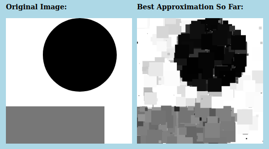
The actual point of the sample program is to try to "evolve" an approximation to a given image, using a "genetic algorithm." (It was inspired by two students from my Fall, 2015 class, Felix Taschbach and Pieter Schaap, who worked on a similar program for their final project, though they didn't use the GPU.) In the program, the average difference between the original image and an approximation is used as a measure of how good the approximation is. I used a very simple grayscale image as the goal, with approximations made from small squares. You don't need to know anything about the genetic algorithm, especially since the program has no practical purpose. However, the source code is heavily commented if you want to try to understand it. Here is a screenshot from one particularly successful run of the program, showing the original image and the best approximation produced after running the genetic algorithm for 7500 generations:
But what interests us here is how the program uses the WebGL floating-point color extensions. The program attempts to activate the extensions during initialization using the following code:
let EXTcbf = gl.getExtension("WEBGL_color_buffer_float");
let EXTtf = gl.getExtension("OES_texture_float");
if (!EXTcbf || !EXTtf) {
   throw new Error("This program requires the WebGL extension" +
           "WEBGL_color_buffer_float, which is not available in this browser.");
}
The program requires the extensions, so an exception is thrown if they can't be activated. The extension objects, EXTcbf and EXTtf, don't have any properties that are needed in this program; however, it is still necessary to call gl.getExtension to activate the extensions.
The program creates two floating-point textures that are attached to framebuffers for use as color buffers. (See Subsection 7.4.2.) Here is the code that creates one of those textures:
tex1 = gl.createTexture();
gl.bindTexture(gl.TEXTURE_2D, tex1);
gl.texImage2D(gl.TEXTURE_2D, 0, gl.RGBA, 256, 256, 0, gl.RGBA, gl.FLOAT, null);
The parameter gl.FLOAT in the last line specifies that the data type for the color components in the texture is float. That data type would be an error if the extensions had not been activated.
When the GPU does the averaging computation with these textures, it is doing floating-point calculations. The program computes a series of smaller and smaller averaged images, stopping with a 4-by-4 pixel image. It then reads the 16 pixel colors back from the texture using the following code:
let data = new Float32Array( 4*4*4 ); // 16 pixels, 4 numbers per pixels
gl.readPixels(0,0,4,4,gl.RGBA,gl.FLOAT,data)
The call to gl.readPixels reads the color data for the 16 pixels into the array, data. Again, the gl.FLOAT parameter specifies the data type, and that parameter value is legal in gl.readPixels only because the extensions have been activated.
7.5.3 Instanced Drawing in WebGL 1.0
Subsection 6.1.7 and Subsection 6.1.8 discussed two features of WebGL 2.0, Vertex Array Objects and instanced drawing. Although these features are not a standard part of WebGL 1.0, both are available as optional WebGL 1.0 extensions. VAOs are enabled by the extension "OES_vertex_array_object", while instanced drawing is enabled by "ANGLE_instanced_arrays". As an example, we look briefly at instanced drawing in WebGL 1.0.
The sample WebGL 1.0 program webgl/instancing-test-webgl1.html uses the instanced drawing extension. It is a copy of the sample WebGL 2.0 program from Subsection 6.1.8, modified to use version 1.0, but with exactly the same functionality. To use instanced drawing in WebGL 1.0, the appropriate extension has to be enabled:
instancedDrawExt = gl.getExtension("ANGLE_instanced_arrays");
if (!instancedDrawExt) {
    throw new Error("WebGL 1.0 Instanced Arrays extension is required.");
}
The extension object, instancedDrawExt, contains functions that are equivalent to the WebGL 2.0 functions for instanced drawing: gl.vertexAttribDivisor(). gl.drawArraysInstanced(), and gl.drawElementsInstanced(). However, the functions are properties of the extension object, not of the graphics context gl, and their names have the word "ANGLE" appended. So, the command
gl.drawArraysInstanced(gl.TRIANGLE_FAN, 0, 64, DISK_COUNT);
from the original WebGL 2.0 program is replaced by
instancedDrawExt.drawArraysInstancedANGLE(gl.TRIANGLE_FAN, 0, 64, DISK_COUNT);
in the WebGL 1.0 program. And
gl.vertexAttribDivisor(a_color_loc,1);
becomes
instancedDrawExt.vertexAttribDivisorANGLE(a_color_loc,1);
Note that, in general, a WebGL 1.0 program that does not use any extensions will work as a WebGL 2.0 program without any modifications. However, if the WebGL 1.0 program uses extensions that are no longer available or no longer needed in WebGL 2.0, some work will be required to convert the program to WebGL 2.0.
7.5.4 Deferred Shading
I will discuss one more WebGL 1.0 extension, one that is useful for an important rendering technique called deferred shading. I don't have a sample program for deferred rendering, and I will only discuss it in general terms.
Deferred shading is used as an optimization when rendering complex scenes, and it is often used to speed up rendering in video games. It is most closely associated with lighting, since it can be used to render scenes with large numbers of light sources, but it can also be useful for other effects.
Recall that the number of lights that can be represented in OpenGL or in a WebGL shader is limited. But scenes with many lights can be rendered using a multi-pass algorithm: Each pass computes the contribution of one light, or a small number of lights, and the results of the passes are added together to give the complete scene. The problem is that, if the rendering in each pass is done in the normal way, then there are a lot of things that have to be recomputed, in exactly the same way, in each pass. For example, assuming that per-pixel lighting is used, that includes computing material properties and a unit normal vector for each pixel in the image. Deferred shading aims to avoid the duplicated effort.
In deferred shading, a first pass is used to compute material properties, normal vectors, and whatever other data is needed, for each pixel in the image. All of that data is saved, to be used in additional passes that will compute lighting and possibly other effects. For a given pixel, only the data for the object that is actually visible at the pixel is saved, since data for hidden surfaces is not needed to render the scene. The first pass uses the geometry and attributes of objects in the scene. Everything that the later passes need to know about geometry and attributes is in the saved data.
The saved data can be stored in texture objects. (Floating point textures are ideal for this, since the data will be used in further calculations.) In this case, the values in the textures don't necessarily represent images. For example, the RGB color components in one texture might represent the x, y, and z coordinates of a normal vector. And if a depth value is needed in later passes, it might be stored in the alpha color component of the same texture. Another texture might hold a diffuse color, while a third holds a specular color in its RGB components and a shininess value in its alpha component. Shader programs are free to interpret data in a texture however they like.
A WebGL shader can write data to a texture, using a framebuffer. But standard WebGL 1.0 can only write to one framebuffer at a time. Now, it would be possible to use a separate pass for each texture that we need to compute, but that would involve a lot of redundant calculations, which is what we are trying to avoid. What we need is a WebGL extension that makes it possible for a shader to write to several framebuffers simultaneously. The extension that we need is named "WEBGL_draw_buffers". When that extension is activated, it becomes possible to attach several textures (or renderbuffers) to a framebuffer, and it becomes possible for a shader to write data to all of the attached shaders simultaneously. The extension is relatively complicated to use. It must be activated, as usual, with a statement of the form
EXTdb = gl.getExtension("WEBGL_draw_buffers");
Assuming that the extension is available, the maximum number of color buffers that can be used in a shader is given by EXTdb.MAX_DRAW_BUFFERS_WEBGL, which will be at least four. With the extension in place, you can attach multiple textures as color buffers for a framebuffer, using code of the form
gl.bindFramebuffer(gl.FRAMEBUFFER, framebuffer);
gl.framebufferTexture2D(gl.FRAMEBUFFER,
     EXTdb.COLOR_ATTACHMENT0_WEBGL, gl.TEXTURE_2D, texture1, 0);
gl.framebufferTexture2D(gl.FRAMEBUFFER,
     EXTdb.COLOR_ATTACHMENT1_WEBGL, gl.TEXTURE_2D, texture2, 0);
and so on, using constants such as EXTdb.COLOR_ATTACHMENT1_WEBGL from the extension object to specify the attachment points.
Usually in a fragment shader, the color that is output to the color buffer is specified by assigning a value to the special variable gl_FragColor. That changes when multiple color buffers are used. In that case, instead of gl_FragColor, the fragment shader has a special variable gl_FragData which is an array of vec4, one for each possible color buffer. Colors are output to the color buffers by assigning values to gl_FragData[0], gl_FragData[1], .... Because this is a change in the legal syntax of the shader, the extension must also be activated in the fragment shader source code by adding the line
#extension GL_EXT_draw_buffers : require
to the beginning of the code. Suppose, for example, that we want to store a normal vector, a diffuse color, a specular color, and object coordinates in the color buffers. Let's say that these values are input to the fragment shader as varying variables or uniform variables, except for the diffuse color, which is sampled from a texture. Then the fragment shader might take the form
#extension GL_EXT_draw_buffers : require
precision highp float;
varying vec3 v_normal, v_objectCoords;
varying vec2 v_texCoords;
uniform vec3 u_specular;
uniform float u_shininess;
uniform sampler2D texture;
void main() {
    gl_FragData[0] = vec4( normalize(v_normal), 0 );
    gl_FragData[1] = vec4( v_object_coords, 1 );
    gl_FragData[2] = texture2D( texture, v_texCoords );
    gl_fragData[3] = vec4( u_specular, u_shininess );
}
The final requirement for using the extension is to specify the correspondence between the indices that are used in gl_FragData and the color buffers that have been attached to the framebuffer. It seems like the correspondence should be automatic, but it's not. You have to specify it using the JavaScript function, EXTdb.drawBuffersWEBGL from the extension object. This function takes an array as parameter, and the values in the array are chosen from the constants EXTdb.COLOR_ATTACHMENT0_WEBGL, EXTdb.COLOR_ATTACHMENT1_WEBGL, .... These are the same constants that are used to specify the color buffer attachment points in a framebuffer. For example, if for some reason you wanted a fragment shader to output to the color buffers that are attached at attachment points 2 and 3, you would call
EXTdb.drawBuffersWEBGL( [
     EXTdb.COLOR_ATTACHMENT2_WEBGL,
     EXTdb.COLOR_ATTACHMENT3_WEBGL
] );
After all that setup, you are ready to do the first pass for deferred shading. For the subsequent passes, you would use a different shader, with a single color buffer. For those passes, you want to run the fragment shader once for each pixel in the image. The fragment shader will use the pixel data that was saved in the first pass, together with other information such as light properties, to compute the output color for the pixel. You can trigger a call to the fragment shader for each pixel simply by drawing a single rectangle that covers the image.
The theory behind deferred shading is not all that complicated, but there are a lot of details to get right in the implementation. Deferred shading is just one of many tricks that are used by video game programmers to improve the rendering speed for their games.
7.5.5 Multiple Draw Buffers in WebGL 2.0
The ability to write to multiple draw buffers is a standard part of WebGL 2.0. The sample program webgl/multiple-draw-buffers-webgl2.html is a simple demonstration. This program takes a sample image and breaks it up into three separate images that show the red, green, and blue color components from the original image. It does that by attaching three textures to a framebuffer, and writing each color component to one of the textures. The image from each texture is then copied to the screen as a grayscale image.
The program has to create and allocate storage for three texture objects, and bind them to a frame buffer as color buffers. Here is the code that does this:
framebuffer = gl.createFramebuffer();
gl.bindFramebuffer(gl.FRAMEBUFFER,framebuffer);
texture0 = gl.createTexture();
gl.bindTexture(gl.TEXTURE_2D, texture0);
gl.texStorage2D(gl.TEXTURE_2D, 1, gl.R8, 320, 399);
gl.framebufferTexture2D(gl.FRAMEBUFFER,
               gl.COLOR_ATTACHMENT0, gl.TEXTURE_2D, texture0, 0);
texture1 = gl.createTexture();
gl.bindTexture(gl.TEXTURE_2D, texture1);
gl.texStorage2D(gl.TEXTURE_2D, 1, gl.R8, 320, 399);
gl.framebufferTexture2D(gl.FRAMEBUFFER,
               gl.COLOR_ATTACHMENT1, gl.TEXTURE_2D, texture1, 0);
texture2 = gl.createTexture();
gl.bindTexture(gl.TEXTURE_2D, texture2);
gl.texStorage2D(gl.TEXTURE_2D, 1, gl.R8, 320, 399);
gl.framebufferTexture2D(gl.FRAMEBUFFER,
               gl.COLOR_ATTACHMENT2, gl.TEXTURE_2D, texture2, 0);
The textures are created with format gl.R8, which stores one eight-bit unsigned integer per pixel; that is sufficient for a grayscale image. (For this format, an 8-bit integer is considered to be scaled to represent a color value in the range 0.0 to 1.0.)
The function gl.drawBuffers() must be called to enable writing to multiple draw buffers and to specify the output destinations. The destinations are specified as an array of attachment points on the framebuffer:
gl.drawBuffers( [
    gl.COLOR_ATTACHMENT0, gl.COLOR_ATTACHMENT1, gl.COLOR_ATTACHMENT2
] );
The shader programs for this example are written in GLSL ES 3.00, which uses out variables in the fragment shader to send output to draw buffers. When there is a single out variable, it automatically sends output to the first draw buffer (draw buffer number zero). When there is more than one out variable, the destination number must be specified for every out variable using a layout qualifier. The location specified for an out variable in the fragment shader is an index into the array of attachment points that was passed to gl.drawBuffers(). As an example, here is the fragment shader from the sample program:
#version 300 es
precision mediump float;
uniform sampler2D u_picture; // texture containing original image
in vec2 v_coords;
layout(location = 0) out float red;   // write to draw buffer 0
layout(location = 1) out float green; // write to draw buffer 1
layout(location = 2) out float blue;  // write to draw buffer 2
void main() {
    vec4 color = texture(u_picture, v_coords);
    red = color.r;
    green = color.g;
    blue = color.b;
}
This fragment shader sends the separate RGB color components from the original image to the three textures that are attached to the framebuffer.
This is a fairly simple and not-very-useful example of using multiple draw buffers, but it does illustrate all the steps that are required to do so.