Section 9.2
Instances and Indices
The previous section showed how to draw one primitive in WebGPU. In this section we will see how to draw more than one primitive in the same image, and we will cover some new options for drawing them: instanced drawing and indexed drawing.
For most of this section, we will be looking at variations on one example: an app that shows randomly colored disks moving around in a canvas. The last variation will add antialiasing to the example using a technique called multisampling. Here is a demo that lets you switch between the basic version and the multisampling version. The edges of the disks in the basic version are more jagged. The effect will be easier to see if you magnify the web page.
9.2.1 Instanced Drawing
Instanced drawing makes it possible to draw multiple copies, or "instances," of the same primitive with a single function call. Instanced drawing in WebGL 2.0 was covered in Subsection 6.1.8. The sample program webgpu/instanced_draw.html shows how to do it in WebGPU. (Again, I urge you to read the comments in the source code for all sample programs!)
The various instances of the primitive can look different in the rendered image, provided that they have different values for some attributes. For example, the instances can have different colors. The color would be an "instance attribute."
We have used the render pass encoder method draw(N) to draw a primitive that has N vertices. For each vertex, the system will pull attribute values from vertex buffers for that vertex and will pass them as parameters to the vertex shader entry point. Instance properties work the same way, except that the value for an instance attribute is the same for every vertex in a given instance.
Instanced drawing uses the same draw() method as regular drawing, but with a second parameter. A call to draw(N,M) will draw M instances of a primitive that has N vertices. The effect is similar to the following pseudocode:
for (i = 0; i < M; i++)
    get instance attribute values for instance i
    for (v = 0; v < N; v++)
       get vertex attribute values for vertex v
       call vertex shader function, passing in all attribute values
(The draw() method can also take two more optional parameters specifying the start index for the vertices and the start index for the instances.)
Vertex attribute values come from vertex buffers. So do instance attribute values. The only difference is a small change in the vertex buffer layout specification. It's time to look at an example. The sample program draws fifty colored disks which a single call to draw(). The basic primitive is a disk centered at (0,0). The coordinates for the vertices of the disk are given as a vertex attribute. Each colored disk is an instance. The color of the disk is an instance attribute. Another instance attribute, offset, specifies a translation transformation that is applied to the primitive. In the shader source code, the vertex coordinates, color, and offset are parameters to the vertex shader function:
@vertex
fn vertexMain(
          @location(0) coords : vec2f,
          @location(1) offset : vec2f,
          @location(2) color : vec3f
       ) -> VertexOutput {
   var output : VertexOutput; // (A struct with position and color fields.)
   output.position = vec4f( coords + offset, 0, 1 );
   output.color = vec4f(color,1);
   return output;
}
Recall that the @location attributes in the parameter list are used to associate the parameters with values coming from the JavaScript side of the program. The association is made by the shaderLocation properties in the vertex buffer layout on the JavaScript side. Here is the layout from the sample program, which specifies the source for each parameter:
let vertexBufferLayout = [
   { // First vertex buffer, for vertex coord.
      attributes: [
        { shaderLocation:0, offset:0, format: "float32x2" }
      ],
      arrayStride: 8,
      stepMode: "vertex"   // This is a vertex attribute.
   },
   { // Second vertex buffer, for instance offsets.
      attributes: [
         { shaderLocation:1, offset:0, format: "float32x2" }
      ],
      arrayStride: 8,
      stepMode: "instance"  // This is an instance attribute.
   },
   { // Third vertex buffer, for instance colors.
      attributes: [
         { shaderLocation:2, offset:0, format: "float32x3" }
      ],
      arrayStride: 12,
      stepMode: "instance"  // This is an instance attribute.
   }
];
As you can see, the only difference between vertex and instance attributes is the value of the stepMode property. Step mode "vertex" tells the system to pull a value from the vertex buffer for each vertex in the primitive. Step mode "instance" means to pull out a value for each instance.
The disks in the sample program can be animated. To draw the next frame in the animation, the program simply computes a new value for the offset attribute of each disk, writes the new values to the vertex buffer that holds the offsets on the GPU side, and then re-renders the image. One technical point about animation might be bothering you: The JavaScript side of the program simply enqueues commands that will be executed later on the GPU side. Somehow, the two sides have to be synchronized, to make sure that we don't start drawing a new image until the old image has been computed and displayed on the web page. That synchronization is taken care of by the requestAnimationFrame() method that is used to implement the animation. That method will not start a new frame until the previous frame is complete.
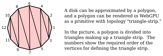
Although it is not related to instanced drawing, another interesting point from the sample program is how it draws a disk. The disk is approximated as a polygon. In WebGL, I would draw the disk as a TRIANGLE_FAN, but WebGPU lacks that primitive type. Here, the disk is drawn using a triangle-strip primitive, which requires a careful ordering of the vertices:
9.2.2 Indexed Drawing
Another way to draw a disk is as a triangle-list primitive, with the disk divided up like the slices of a pie. The vertices for one of the triangles would be the center of the disk plus two consecutive vertices on the circumference. Note that a given vertex can be used in several different triangles. This means that the disk can be implemented most efficiently as an indexed face set. The data for an indexed face set consists of a list of vertex coordinates (plus corresponding lists of values for other vertex attributes if needed) and a list of vertex indices. (See Subsection 3.4.1 for the more details.)
A WebGPU render pass encoder has a drawIndexed(N) method that implements this type of drawing. In addition to vertex buffers, this method requires an index buffer to hold the vertex indices. The values in the index buffer must be either 16-bit unsigned integers or 32-bit unsigned integers. The effect of drawIndexed(N) is
for (i = 0; i < N; i++)
    Let v be index number i from the index buffer
    get attribute values for vertex v from the vertex buffers
    call the vertex shader function, passing in the attribute values
The sample program webgpu/indexed_draw.html draws a single disk as a triangle-list primitive using drawIndexed(). To add a little interest, it also draws the circumference of the disk as a line-strip primitive, using the basic draw() method. So the same program also shows how to render two primitives in the same render pass.
In the program, VERTEX_COUNT is the number of vertices of the polygon that is used to approximate the disk. The vertices are numbered in counterclockwise order around the disk, with vertex number 0 repeated at the end. The VERTEX_COUNT+1 vertices can then be used in order to draw the outline of the disk as a line-strip. For drawing the interior of disk, we will also need to have the center of the disk, (0,0), in the list. The center is added as vertex number VERTEX_COUNT+1. To render the interior, we need to draw 3*VERTEX_COUNT vertices—three vertices for each triangle. The data for the index buffer is loaded into a JavaScript Uint16Array of length 3*VERTEX_COUNT:
/* Fill diskIndices with the vertex indices for the VERTEX_COUNT
 * triangles that make up the disk.  Each triangle uses the center
 * of the disk and two consecutive vertices on the outline. */

for (let i = 0; i < VERTEX_COUNT; i++) {
    diskIndices[3*i] = VERTEX_COUNT+1;  // center of disk
    diskIndices[3*i+1] = i;             // vertex number i
    diskIndices[3*i+2] = i+1;           // vertex number i+1
}
A buffer is created to hold the indices on the GPU side, and the values in diskIndices are written to that buffer:
indexBuffer = device.createBuffer({
     size: diskIndices.byteLength,
     usage: GPUBufferUsage.INDEX | GPUBufferUsage.COPY_DST
  });
device.queue.writeBuffer(indexBuffer, 0, diskIndices);
The GPUBufferUsage.INDEX indicates that the buffer will be used as an index buffer. Otherwise, this is the same as creating a vertex buffer. But unlike vertex buffers, an index buffer is not attached to a pipeline. Instead, it is specified when creating the render pass:
passEncoder.setIndexBuffer(indexBuffer, "uint16");
The second parameter says that the indices are 16-bit unsigned integers; the alternative is "uint32" for 32-bit integers.
It will be worthwhile to look at the full code for rendering the disk interior and outline. The interior and the outline use different primitive topologies. Since the primitive topology is a property of the render pipeline, we need to use separate pipelines for the interior and for the outline. Since the pipeline is an aspect of a rendering pass, we need to encode two render passes:
function draw() {
   let commandEncoder = device.createCommandEncoder();
   let renderPassDescriptor = {
      colorAttachments: [{
          clearValue: { r: 1, g: 1, b: 1, a: 1 }, // White background.
          loadOp: "", // To be assigned later!
          storeOp: "store",
          view: context.getCurrentTexture().createView()
      }]
   };

   /* First render pass draws the disk, using a "triangle-list" topology. */

   renderPassDescriptor.colorAttachments[0].loadOp = "clear";
   let passEncoder = commandEncoder.beginRenderPass(renderPassDescriptor);
   passEncoder.setPipeline(pipelineForDisk); // uses "triangle-list"
   passEncoder.setVertexBuffer(0,vertexBuffer);
   passEncoder.setIndexBuffer(indexBuffer, "uint16");
   passEncoder.drawIndexed( 3*VERTEX_COUNT ); // 3 vertices per triangle.
   passEncoder.end();

   /* Second render pass draws the outline, using a "line-strip" topology. */

   renderPassDescriptor.colorAttachments[0].loadOp = "load"; // DON'T clear!
   passEncoder = commandEncoder.beginRenderPass(renderPassDescriptor);
   passEncoder.setPipeline(pipelineForOutline); // uses "line-strip"
   passEncoder.setVertexBuffer(0,vertexBuffer);
   passEncoder.draw(VERTEX_COUNT+1);
   passEncoder.end();

   let commandBuffer = commandEncoder.finish();
   device.queue.submit([commandBuffer]);
}
Note that for the first render pass, the loadOp is "clear", since we want to fill the image with the background color before rendering the disk. For the second render pass, we want to draw the outline on top of the existing image, so the loadOp must be "load". The same renderPassDescriptor can be used for both passes, with just the loadOp property changed.
9.2.3 Drawing Multiple Primitives
I would like to draw the outlines of the colored disks in my moving disk example. However I can't simply use instanced drawing to draw all the disks, then use it again to draw the outlines, since that would show the complete outline of every disk, even parts of the outline that should be hidden by other disks. (Actually, I can do that if I add a depth test to the program (see Subsection 9.4.1).) A solution is to abandon instanced drawing and draw each disk separately. That's what I do in the sample program webgpu/draw_multiple.html. That program also introduces a few new WebGPU features.
Each disk in the new program is drawn in the same way as the single disk in webgpu/indexed_draw.html. The problem is that the disks have different colors and offsets. In webgpu/instanced_draw.html, the color and offset were instance properties that came from vertex buffers, and their values were passed as parameters into the vertex shader function. In the new program, they are moved into a uniform variable in the shader program:
struct DiskInfo {
    color : vec3f,  // interior color for the disk
    offset : vec2f  // translation applied to the disk
}

@group(0) @binding(0) var<uniform> diskInfo : DiskInfo;
The values for the uniform variable are stored in a uniform buffer. Before drawing each disk, the color and offset for that disk must be copied into the uniform buffer. The basic idea is simple:
for each disk:
    copy offset and color for that disk to the uniform buffer
    do a render pass to draw the disk interior
    do a render pass to draw the disk outline
Previously, we have used device.queue.writeBuffer() to copy data from the JavaScript side into a buffer on the GPU. That would work, provided that we use a new command encoder for each iteration of the loop. (In fact, that's what I do in an alternative version of the program, webgpu/draw_multiple_2.html. See the comments in that program for more information.)
However, I decided to complicate things—and hopefully make the program a little more efficient—by using a single command encoder to do all the drawing. But that makes it impossible to use writeBuffer(). Let's see why. A command encoder doesn't execute commands, it just makes a list of commands that will be submitted to the device queue in a batch after the list is complete. Similarly, when writeBuffer() is called, it doesn't immediately write to the buffer. But it does immediately add a command to the device queue to do the writing. If we do the calls to writeBuffer() in the middle of collecting the draw commands in a command encoder, then when we submit the draw commands in a batch at the end, all the write commands will already be in the queue. So, all of the write commands will actually be executed before any the draw commands. Only the final write will have any effect on the drawing!
The solution is to replace writeBuffer() with a copy command that can be encoded and added to the list of commands produced by a command encoder. Then, when the list of commands is executed on the GPU, each copy will be done just before the draw command that uses it. But since the copying will be done on the GPU, the data that is being copied must already be in a GPU buffer. The command that we want is
commandEncoder.copyBufferToBuffer( destinationBuffer, destinationStartByte,
        sourceBuffer, sourceStartByte, byteCount );
To implement this, the program copies the color values for all the disks into a GPU buffer, and copies the offset values into another GPU buffer. Using buffers for these values is similar to what we did for instanced drawing, but the buffers in this case are not vertex buffers. Instead, they are storage buffers, a kind of general purpose GPU buffer. They can be used much like uniform buffers but have fewer restrictions and might be a little less efficient. Here is how the storage buffer for the disk colors is created and filled with data as part of program initialization:
diskColorBuffer =  device.createBuffer({
    size: diskColors.byteLength,
    usage: GPUBufferUsage.STORAGE |
                  GPUBufferUsage.COPY_SRC | GPUBufferUsage.COPY_DST
});
device.queue.writeBuffer(diskColorBuffer, 0, diskColors);
The usage property includes STORAGE because the buffer is a storage buffer; it includes COPY_SRC so that the buffer can be used as the source buffer in copyBufferToBuffer(); and it includes COPY_DST so that the buffer can be used as the destination buffer in writeBuffer().
When a storage buffer is used in a shader program, it must be part of a bind group. In this program, however, the storage buffers are not used in the shaders, and the only thing in the bind group is the small uniform buffer that holds the color and offset for one disk at a time.
The command for copying the color for disk number i from the storage buffer to the uniform buffer then becomes
commandEncoder.copyBufferToBuffer( diskColorBuffer, 12*i,
                                             uniformBuffer, 0, 12 );
The color data in diskColorBuffer for each disk takes up 12 bytes (three 32-bit floats), so the starting byte for the color for disk number i is 12*i. In uniformBuffer, the color starts at byte number 0. And the byte count, 12, is the number of bytes to be copied.
The disk offset is handled in a similar way, but there is one more issue to deal with: alignment rules in WGSL. Alignment refers to restrictions on where a value can be located in memory. The restrictions can make memory access more efficient. For example, the alignment rule for a vec2f says that its address in memory must be multiple of 8 bytes. The uniform variable, diskInfo, is a struct that contains a vec3f for the color followed by a vec2f for the offset. The vec3f takes up 12 bytes in memory. But the alignment rule for the vec2f says that it must start at a multiple of 8 bytes. So, an extra byte of padding is added after the color, moving the starting byte number for the offset to 16. When the offset is copied from the storage buffer to the uniform buffer, the starting byte is 16, rather than the 12 that you might have expected:
commandEncoder.copyBufferToBuffer( diskOffsetBuffer, 8*i,
                                             uniformBuffer, 16, 8 );
I will have more to say about alignment in Subsection 9.3.1. You should be able to understand the rest of the program source. As always, read the comments.
9.2.4 Using Indices in Shaders
In WebGL, each point in a primitive of type POINTS can have a size. The point is rendered as a square with the given size, and the square comes with texture coordinates. (See Subsection 6.2.5.) In WebGPU, there is no similar idea of point size for primitives with the point-list topology; the points are just individual pixels, which limits their usefulness.
Now, in WebGPU, we could easily use instanced drawing to render multiple copies of a square and do something very similar to the WebGL POINTS primitive. However, I would like to use a different approach, to illustrate a new WebGPU feature: using vertex and instance indices in shaders. I do that in the sample program webgpu/indices_in_shader.html, which shows the same moving disks as the first example in this section but does so in a very different way.
We have seen how parameter values for a vertex shader function can come from vertex buffers. But there are also certain "builtin" values that can be used as parameters. This includes the vertex index and the instance index of the vertex that is being processed. For example, the definition of the vertex shader function in the sample program is
@vertex
fn vertMain(
    @builtin(vertex_index) vertexNumInPoint: u32,
    @builtin(instance_index) pointNum: u32
) -> VertexOutput { . . .
If this function is invoked by a call to draw(vertexCt,instanceCt) in a render pass encoder, the effect is similar to this pseudocode:
for (instance_index = 0; instance_index < instanceCt; instance_index++)
    for (vertex_index = 0; vertex_index < vertexCt; vertex_index++)
        vertMain( instance_index, vertex_index )
Note that in this example there are no parameter inputs from vertex buffers. But the job of the function is still to output coordinates and possibly other data for vertex number vertex_index in instance number instance_index. It needs to create that output somehow!
The shader still has access to data from other sources, such as buffers that are part of bind groups. In this example, I provide the necessary data in two storage buffers. One storage buffer contains a color for each square, and one contains the coordinates of the center point for each square. The size of the square is a constant in the shader program. The output for a vertex consists of coordinates, texture coordinates, and color for that vertex. Each instance is a square, generated as a triangle-list primitive with two triangles, so that the number of vertices in an instance is six. The coordinates and texture coordinates for each vertex can be computed from the center point and the size of the square:
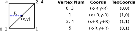
For each instance, the vertex shader function is invoked six times, with a vertex index ranging from 0 to 5. In each invocation, the shader function computes and outputs the appropriate values for just one vertex. I won't go into the coding details here; you can read them in the sample program source code.
There is one more point of interest in the program: I really wanted to draw disks, not squares, and I wanted to have some use for the texture coordinates on the square. So the fragment shader function uses the texture coordinates for a pixel to discard that pixel if it lies outside the disk. (This is similar to what was done in WebGL for the demo in Subsection 6.4.2.)
9.2.5 Multisampling
The final example for this section is webgpu/multisampling.html, which adds multisampling to the basic moving disks example. Ordinarily, the fragment shader entry point function is evaluated once per pixel, at the center point of the pixel. With multisampling, it is evaluated at several points within each pixel, and the color for that pixel is obtained by averaging the colors from each of those samples. This is a kind of antialiasing. For example, when the geometric edge of a primitive cuts through a pixel, some sampled points might lie inside the primitive and some outside. The color of the pixel will then be a blend of the primitive color and the background color. Or, when a texture is applied, the texture color for the pixel will be a blend of the texture colors at the sampled points.
WebGL will do antialiasing automatically, but in WebGPU, you have to do some work. Fortunately, it's not very hard. There are just a few changes from a non-multisampled program. First, you need a texture for multisampling, and a view of that texture. (I will admit that I don't understand why this is needed.) The code for that is a preview of creating textures and texture views:
textureForMultisampling = device.createTexture({
    size: [context.canvas.width, context.canvas.height],
    sampleCount: 4,  // (1 and 4 are currently the only possible values.)
    format: navigator.gpu.getPreferredCanvasFormat(),
    usage: GPUTextureUsage.RENDER_ATTACHMENT,
});
textureViewForMultisampling = textureForMultisampling.createView();
When drawing the image, the multisampling texture view is used as the view property in the color attachment of the render pass descriptor. And the usual value of that view property, which represents the final image, is moved to a new resolveTarget property:
renderPassDescriptor = {
   colorAttachments: [{
      clearValue: { r: 0.9, g: 0.9, b: 0.9, a: 1 },
      loadOp: "clear",
      storeOp: "store",
      view: textureViewForMultisampling, // Render to multisampling texture.
      resolveTarget: context.getCurrentTexture().createView() // Final image.
   }]
};
And finally, a new multisample property must be added to the render pipeline descriptor, to specify that the pipeline does multisampled rendering:
pipelineDescriptor = {
         . . .
    multisample: {  // Sets number of samples for multisampling.
       count: 4,     //  (1 and 4 are currently the only possible values).
    },
       . . .
And that's it! (Later, we'll see that when multisampling is applied to a program that uses the depth test, one more small change in necessary, in the depth buffer configuration.)