This page contains questions and answers for the second quiz in CS100: Principles of Computer Science, a course based on the book The Most Comples Machine.
The answers given here are sample answers only. There is always some variation in the answers that would receive full credit. The Notes contain any extra comments I happen to have; they are not parts of the answers.
Question 1: In each of the following circuits, label the output wire of each logic gate as either ON or OFF.
Answer: Here is the circuit, with the output wires labeled:

Question 2: Draw the logic circuit corresponding to the Boolean algebra expression:
(A and B) or ((not C) and (A or B))
Answer:Here is the circuit, with wires labeled to show the corresponding expression.

Question 3: Add the following two 16-bit binary numbers:
              0 0 0 0 0 0 0 0 1 1 0 1 1 0 0 1
              0 0 0 0 0 1 0 0 1 1 0 0 0 1 1 1
              -------------------------------
Answer: The sum is 0000011011010000.
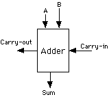
Question 4: Shown below is a full adder circuit. Explain the purpose of this circuit, and explain the purpose of each of its input and output wires.

Answer: This circuit adds three one-bit binary numbers and
produces a two-bit binary number as an answer. The three bits that
are to be added are input on the wires labeled A, B and Carry-in.
The two bits of the answer are output on the Sum wire and the Carry-out
wire. When multi-bit numbers are added, as in problem 3 above,
one adder circuit like this one is used to compute the sum of each
column in the problem. A and B represent the two bits in the column.
The Carry-in is a bit carried over from the column to the right,
and the Carry-out is then carried over to be added to the column
to the left.
Question 5: "If you can specify the desired output of a logic circuit for each possible combination of inputs, then it is possible to build a logic circuit that has that specified behavior." Carefully explain how we know that this statement is true.
Answer: The specification of the circuit can be used to make an "input/output table" that shows what the output of the circuit should be for each possible combination of inputs. From this, you can write down a Boolean algebra expression that describes the circuit. Once you have that expression, it can be used as blueprint for a circuit that has the specified behavior. The steps "input/output table to Boolean expression to circuit" can be done mechanically, without thought, so we know that they can always be done. (However, this method will usually give a circuit that is much more complicated than it has to be. Thinking is still good for something!)