last updated: --Thu Feb 9 14:18:10 EST 2006--
page owned by: bridgeman@hws.edu
| CPSC 324 | Fundamentals of Computer Graphics | Spring 2006 |
This document describes the file format used for writing scene description files.
The scene graph structure described in the CPSC 324 Renderer scene graph files is a little different from the structure built up in the scene graph builder applet in the homework. This is due, in part, to the need to accomodate additional elements like cameras, lights, and materials in the scene graph files. The CPSC 324 Renderer structure is similar to that used by Open Inventor, a high-level 3D graphics package from SGI.
The following examples compare the scene graph builder applet scene graph and the CPSC 324 Renderer scene graph structure for similar scenes involving a robot figure.
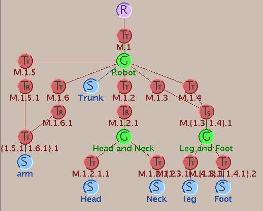

In the scene graph builder applet scene graphs, transformations are applied from the bottom up e.g. the modeling transform for the head is M.1 M.1.2 M.1.2.1 M.1.2.1.1. (Remember that matrices are premultiplied.) Also, group nodes were used for conceptual grouping and to create branches.
(Note this is not the simplest scene graph which produces the robot figure - M.1, M.1.2.1, and M.{1.3|1.4}.1 are included only to facilitate experimentation and are not necessary for constructing the robot.)
For starters, the CPSC 324 Renderer scene graph includes additional nodes such as cameras, lights, and materials. The fundamental difference, however, is how the effect of each material and transform node is computed. There are two main rules:
For transforms, this amounts to building the modeling transform from the top down and from left-to-right - opposite of the scene graph builder applet.
For example, the modeling transform for the first occurrence of shape S6 is T7 T6 (i.e. the transforms are applied in the order T6, then T7) and for the second occurrence of S6 is T8 T7 T6. Another example is shape S5 - the modeling transform is T4 T3 for its first occurrence and T4 T5 T3 for the second. T3 and T5 affect S5 because they affect G3 and so are inherited by G3's children.
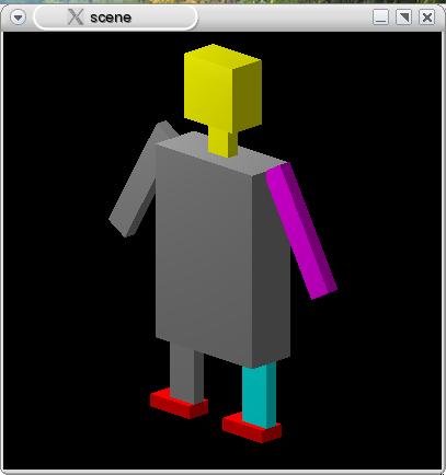
Since materials can't accumulate, only the most recently encountered material is in effect. For example, the head and neck (shapes S2 and S3) are both yellow because material M1 is to the left of shapes S2 and S3 among the children of group node G1. The rest of the robot is not yellow, however, because placing M1 as a child of G1 limits its effect to only descendants of G1. Also, child nodes are processed from left to right, so only the right arm is purple - shape S6 generates both the left and right arms because it is included twice as a child of G4, but only the second occurrence is after material M4. Similarly, the feet are red (and not the legs) because shape S4 (the leg) is listed before M2 while shape S5 (the foot) is after M2 in the children of G3. The most complex case in this scene graph is the right leg - it is cyan because material M3 applies to only the second occurrence of group G3 (the leg and foot combination). The right foot is not also cyan because only shape S4 (the leg) is affected by the material in effect for G3 - material M2 replaces the current setting in time for shape S5 (the foot).
The CPSC 324 Renderer scene file format is written in XML, in part because XML parsers are readily available. (XML is also relatively easy to write, and some validity-checking is built into the parsing process.) (what is XML?) XML syntax is similar to HTML syntax, so you will find aspects of XML familiar if you have used HTML.
XML is a language for giving structure to information. This structure is defined via nested tags. Unlike HTML, every open tag must be matched with a close tag. Tags may also have attributes. (quick introduction to basic XML syntax and attributes) In the CPSC 324 Renderer scene files, there will not be any text (other than a couple of headers) which is neither a tag nor an attribute.
| XML syntax | meaning |
|---|---|
<sphere tessellation="16,16"></sphere> | Example of the sphere tag. tessellation="16,16" is an attribute, and is specified as part of the open tag. </sphere> is the corresponding close tag. |
<sphere tessellation="16,16"/> | If there is nothing between the open tag and close tag, XML allows an abbreviated syntax in which /> acts as the close tag - this is equivalent to the previous example. |
XML files are typically named with a .xml extension (e.g. myfile.xml). You should use this convention with scene files that you create.
A "well-formed" XML document is one which has correct XML syntax (e.g. all tags are properly closed and nested). A "valid" XML document is one whose structure conforms to that specified by a Document Type Definition (DTD) or schema. The DTD specifies which tags are legal, what attributes they may have, default values for attributes which are omitted, and how tags may be nested. The scene graph DTD is defined in /classes/s06/cs324/scenes/scenegraph.dtd - you can check it out if you are curious. Its rules, however, are described below so you don't need to read the DTD itself.
Many elements of XML syntax and the scene file format are most easily explained via examples.
Consider the following scene and scene graph:
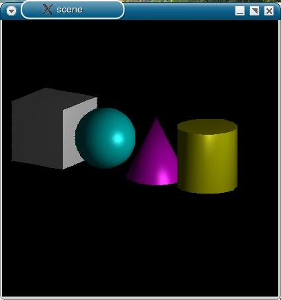
Keep in mind that only the most-recently-encountered material is in effect, but the transformations accumulate.
This scene graph is represented by the following file:
<?xml version="1.0"?> <!DOCTYPE scene SYSTEM "/classes/s06/cs324/scenes/scenegraph.dtd"> |
Every scene file will start with these two lines. The first line (the XML declaration) defines what version of XML is used in the document. (It may also contain other information, such as the character set used.) The second line specifies the location of the DTD which specifies the structure of this document. "scene" indicates the name of the root element in the structure, and "/classes/s06/cs324/scenes/scenegraph.dtd" is the filename of the DTD. A URL may may used in place of a filename. |
<scene> |
The scene tag is the root element of the structure - all of the scene description is contained between the open and close scene tag. |
  <camera type="parallel" vrp="0,0,2" lookat="-2,-1,-1" vup="0,1,0"
	  frontclip="-1" backclip="-3" viewplane="0" width="9" aspectRatio="1">
    <projection prp="1,0,4" dop="0,0,1"/>
  </camera>
|
The camera tag describes the camera and projection. It must be the first element in the scene, and there must be one (and only one) camera tag. The attributes describe most of the camera's properties. The nested projection tag describes the parameters of the projection (the PRP and DOP, or equivalently the alpha and phi angles). |
  <lights>
    <ambient on="true" intensity="1" color="1,1,1"/>
    <point on="true" intensity="1" location="6,2,2"/>
  </lights>
|
The next element must be a lights tag (if one is present), which describes the scene's lighting. It contains zero or more nested tags describing individual lights. This particular lights tag contains two nested lights - an ambient light and a point light. |
  <material diffuseColor="1,1,1" specularFrac=".5"
	    ambientRefl=".2" diffuseRefl=".9" specularRefl=".9"
            specularExp="10"/>

  <transform>
    <translate vector="-3.5,0,0"/>
  </transform>

  <cube/>

  <material diffuseColor="0,1,1" specularFrac=".5"
	    ambientRefl=".2" diffuseRefl=".9" specularRefl=".9"
            specularExp="10"/>

  <transform>
    <translate vector="2,0,0"/>
  </transform>

  <sphere/>

  <material diffuseColor="1,0,1" specularFrac=".5"
	    ambientRefl=".2" diffuseRefl=".9" specularRefl=".9"
            specularExp="10"/>

  <transform>
    <translate vector="2,0,0"/>
  </transform>

  <cone/>

  <material diffuseColor="1,1,0" specularFrac=".5"
	    ambientRefl=".2" diffuseRefl=".9" specularRefl=".9"
            specularExp="10"/>

  <transform>
    <translate vector="2,0,0"/>
  </transform>

  <cylinder/>
|
The remaining tags describe the elements in the scene. In this scene graph, all of the materials, transforms, and objects (cube, sphere, cone, cylinder) are children of the scene graph root because these tags are nested directly under the root scene tag. Not that just as the camera, lights, material, transform, and shape nodes are all shown as children of the scene node in the scene graph, all of these tags are nested directly under the scene tag. Furthermore, keep in mind that the transforms accumulate - so, for example, the sphere is centered at (-1.5,0,0). |
</scene> |
The </scene> tag ends the scene description. |
The second example illustrates the robot scene graph.
<?xml version="1.0"?>
<!DOCTYPE scene SYSTEM "scenegraph.dtd">

<scene version="1.1">

  <camera type="parallel" vrp="2,1,2" lookat="0,0,0" vup="0,1,0"
	  frontclip="-1" backclip="-3" viewplane="0" width="16" aspectRatio="1">
    <projection prp="0,0,20" dop="0,0,1"/>
  </camera>

  <lights>
    <ambient on="true" intensity="1" color="1,1,1"/>
    <point on="true" intensity="1" location="-8,12,8"/>
    <point on="true" intensity="1" location="-8,12,3"/>
  </lights>

  <cube height="7.5" width="5" depth="2" name="trunk"/>
| |
<group> |
group tags serve several purposes. In this case it is being used as a "separator", so that materials and transforms used to build the head and neck are isolated from the rest of the scene graph and don't affect the other elements. |
    <material diffuseColor="1,1,0" specularFrac=".2"
              ambientRefl=".9" diffuseRefl=".9" specularRefl=".9"
              specularExp="30"/>

    <transform>
      <translate vector="0,4.375,0"/>
    </transform>

    <cube height="1.25" width="1" depth=".5" name="neck"/>

    <transform>
      <translate vector="0,1.875,0"/>
    </transform>

    <cube height="2.5" width="2.5" depth="1.5" name="head"/>
  </group>
|
The head and heck - since these materials and transforms are nested within a group tag, their effect is limited to the two cubes. Geometry objects (such as cubes) can be named, though here the name is used only to make the file easier to read. Names must be unique within a scene graph. |
  <group>
    <transform>
      <translate vector="-1.875,-5,0"/>
    </transform>
| |
    <group name="leg+foot">
      <cube height="2.5" width="1.25" depth=".5" name="leg"/>

      <transform>
        <translate vector="-.375,-1.5,0"/>
      </transform>

      <material diffuseColor="1,0,0" specularFrac=".2"
                ambientRefl=".9" diffuseRefl=".9" specularRefl=".9"
                specularExp="30"/>

      <cube height=".5" width="2" depth="1" name="foot"/>
    </group>
|
Here the group is named because it will be referred to later... |
    <transform>
      <translate vector="3.75,0,0"/>
    </transform>

    <material diffuseColor="0,1,1" specularFrac=".2"
              ambientRefl=".9" diffuseRefl=".9" specularRefl=".9"
              specularExp="30"/>
| |
<object name="leg+foot"/>
|
The object tag allows a previously-named object to be repeated, without copying all of the structure that went into it. The name to which the "name" attribute refers must have already been defined. In this case, this generates the second leg and foot. |
  </group>

  <group>
    <transform>
      <rotate angle="-30"/>
      <translate vector="-4,1.75,0"/>
    </transform>

    <cube height="5" width="1" depth=".5" name="arm"/>

    <transform>
      <scale factor="-1,1,1"/>
    </transform>

    <material diffuseColor="1,0,1" specularFrac=".2"
              ambientRefl=".9" diffuseRefl=".9" specularRefl=".9"
              specularExp="30"/>

    <object name="arm"/>
  </group>

</scene>
|
The default value, if any, is used if the attribute is omitted (though in many cases it is recommended to include all of the attributes even if the default value is desired, because it makes it easier to read the scene file). Attributes without default values are optional.
Some tags and attributes are only supported in certain versions of the scene file format. The renderer will print out the version it is using when it starts up (e.g. "creating scene v. 1.1"). If no message is printed, it is using v. 1.0. All updates are backwards-compatible i.e. a renderer using v. 1.0 will be able to successfully parse v. 1.1 scene files - it will just ignore v. 1.1 tags/attributes. A warning is printed if the scene file version is newer than the version supported by the renderer.
<scene> is the root tag. Attributes:
| attribute | meaning | legal values | default value |
|---|---|---|---|
| version | scene file format version used in this file | any sequence of integers separated by dots e.g. 2.3.1.2 | 1.0 |
Note: the attribute version is supported in v. 1.1 and higher of the scene graph file format. This attribute is included for informational purposes only - there is no check or enforcement that the scene file actually uses only tags/attributes applicable to the specified version.
  <camera type="parallel" vrp="0,0,2" lookat="-2,-1,-1" vup="0,1,0"
	  frontclip="-1" backclip="-3" viewplane="0" width="9" aspectRatio="1">
    <projection prp="1,0,4" dop="0,0,1"/>
  </camera>
The <camera> tag describes the camera and projection. It must be the first element in the scene, and there must be one (and only one) <camera> tag. The attributes describe most of the camera's properties:
| attribute | meaning | legal values | default value |
|---|---|---|---|
| type | type of projection | parallel perspective | parallel |
| vrp | VRP (WC) | any point | 0,0,0 |
| lookat | look at point (WC) | any point | 0,0,-1 |
| vup | VUP vector (WC) | any vector not parallel to the VPN | 0,1,0 |
| viewplane | z coordinate of view plane (VC) | any value not equal to PRPz (though should generally be < PRPz) | 0 |
| frontclip | z coordinate of front clipping plane (VC) | any value (though should generally be ≤ viewplane) | 0 |
| backclip | z coordinate of back clipping plane (VC) | any value < frontclip | -1 |
| width | width of view window (VC) | > 0 | 1 |
| aspectRatio | aspect ratio (width/height) of view window (VC) | > 0 | 1 |
A single nested tag is required, and may be either projection or projectionalt. (The difference between projection and projectionalt is how the DOP is specified.)
This tag is used to specify the PRP and DOP.
  <camera type="parallel" vrp="0,0,2" lookat="-2,-1,-1" vup="0,1,0"
	  frontclip="-1" backclip="-3" viewplane="0" width="9" aspectRatio="1">
    <projection prp="1,0,4" dop="0,0,1"/>
  </camera>
In this form, the DOP is specified directly by a vector. Attributes:
| attribute | meaning | legal values | default value |
|---|---|---|---|
| prp | PRP (VC) | any point not in the view plane (though typically PRPz > viewplane) | 0,0,1 |
| dop | DOP | DOPz > 0 | 0,0,1 |
This tag is used to specify the PRP and DOP.
  <camera type="parallel" vrp="0,0,2" lookat="-2,-1,-1" vup="0,1,0"
	  frontclip="-1" backclip="-3" viewplane="0" width="9" aspectRatio="1"camera type="parallel" vrp="0,0,2" lookat="-2,-1,-1" vup="0,1,0"
	  frontclip="-1" backclip="-3" viewplane="0" width="9" aspectRatio="1">
    <projectionalt prp="1,0,4" alpha="45" phi="30"/>
  </camera>
In this form, the DOP is specified by alpha and phi angles. Attributes:
| attribute | meaning | legal values | default value |
|---|---|---|---|
| prp | PRP (VC) | any point not in the view plane (though typically PRPz > viewplane) | 0,0,1 |
| alpha | alpha angle | 0 < alpha < 180 | 90 |
| phi | phi angle | any angle | 0 |
The <lights> tag describes the lights present in the scene. It is optional, though without it most scenes will appear completely black (the only exception is for renderers such as wireframe which do not take lighting into account). If present, it must follow the <camera> tag.
The <lights> tag itself has no attributes; it serves only to group the individual lights together.
The <ambient> tag describes an ambient light. It must be a child of <lights>. It is legal to include multiple ambient lights in a scene, though this doesn't really make sense to do. Attributes:
| attribute | meaning | legal values | default value |
|---|---|---|---|
| on | whether or not the light is on (if off, light does not contribute to scene's lighting) | true false | true |
| intensity | how "on" the light is | 0 ≤ intensity ≤ 1 | 0 |
| color | the color of the light | any legal color | 1,1,1 |
The light's actual color (i.e. the values used in lighting) is the product of the intensity and the color. While the intensity is redundant, it is included to make it easier to adjust the lighting - set the color to the full-bright color, and use the intensity to turn it down as needed.
The <point> tag describes a point light. It must be a child of <lights>. Multiple point lights may be included in a scene. Attributes:
| attribute | meaning | legal values | default value |
|---|---|---|---|
| on | whether or not the light is on (if off, light does not contribute to scene's lighting) | true false | true |
| intensity | how "on" the light is | 0 ≤ intensity ≤ 1 | 1 |
| color | the color of the light | any legal color | 1,1,1 |
| location | position of the light (WC) | any position | 0,0,0 |
| attenutation | coefficients for the constant, d, and d2 terms in the attenuation function | any value | 1,0,0 |
The light's actual color (i.e. the values used in lighting) is the product of the intensity and the color. While the intensity is redundant, it is included to make it easier to adjust the lighting - set the color to the full-bright color, and use the intensity to turn it down as needed.
The <material> tag describes a material. Attributes:
| attribute | meaning | legal values | default value |
|---|---|---|---|
| diffuseColor | the object's diffuse color (what is typically thought of as the object's color) | any color | 1,1,1 |
| specularFrac | what percentage of the object's color contributes
to the specular color 1 = all object's color, 0 = all light's color | 0 ≤ specularFrac ≤ 1 | 1 |
| ambientRefl | percentage of ambient light reflected | 0 ≤ ambientRefl ≤ 1 | .5 |
| diffuseRefl | percentage of diffuse light from light sources reflected | 0 ≤ diffuseRefl ≤ 1 | .5 |
| specularRefl | percentage of specular light from light source reflected | 0 ≤ specularRefl ≤ 1 | .5 |
| specularExp | specular exponent 1 = matte surface, > 100 = very shiny | ≥ 1 | 10 |
| reflection | percentage of incoming light ray (other than from light sources) reflected | 0 ≤ reflection ≤ 1 | 0 |
| transparency | percentage of incoming light ray (other than from light sources) transmitted through the object | 0 ≤ transparency ≤ 1 | 0 |
| refractionIndex | refraction index | ≥ 1 | 1.0 |
The <transform> tag describes a series of transforms. It has no attributes, and serves only to group together a set of transforms. It contains zero or more translate, rotate, or scale elements.
The <translate> tag describes a translation. Attributes:
| attribute | meaning | legal values | default value |
|---|---|---|---|
| vector | the translation vector | any legal vector | 0,0,0 |
The <rotate> tag describes a general rotation. Attributes:
| attribute | meaning | legal values | default value |
|---|---|---|---|
| point | the fixed point | any legal point | 0,0,0 |
| axis | vector pointing along the axis of rotation | any legal vector with length > 0 | 0,0,1 |
| angle | counterclockwise angle to rotate, in degrees | any angle | 0 |
The <scale> tag describes a general scale. Attributes:
| attribute | meaning | legal values | default value |
|---|---|---|---|
| factor | the scale factors | in the form factor (for a uniform scale) or xfactor,yfactor,zfactor | 1,1,1 |
| point | the fixed point | any legal point | 0,0,0 |
The single factor value form is only available in v. 1.1 and higher of the scene graph file format.
The <cube> tag describes an axis-aligned cube centered at the origin. Attributes:
| attribute | meaning | legal values | default value |
|---|---|---|---|
| width | the cube's width (x dimension) | > 0 | 2 |
| height | the cube's height (y dimension) | > 0 | 2 |
| depth | the cube's depth (z dimension) | > 0 | 2 |
| name | name for this object | any string | |
| tessellation | number of divisions along each face of the cube when the cube is turned into a triangle mesh | integer ≥ 1 | 8 |
Note: the attributes width, height, and depth are supported in v. 1.1 and higher of the scene graph file format.
The <sphere> tag describes a sphere centered at the origin. Attributes:
| attribute | meaning | legal values | default value |
|---|---|---|---|
| radius | the sphere's radius | > 0 | 1 |
| name | name for this object | any string | |
| tessellation | number of divisions when the sphere is turned into a triangle mesh, along the latitude and longitude lines respectively | integer ≥ 1 | 16,16 |
Note: the attribute radius is supported in v. 1.1 and higher of the scene graph file format.
The <cylinder> tag describes a cylinder centered at the origin with its height along the y axis. Attributes:
| attribute | meaning | legal values | default value |
|---|---|---|---|
| radius | the cylinder's radius | > 0 | 1 |
| height | the cylinder's height (y direction) | > 0 | 1 |
| name | name for this object | any string | |
| tessellation | number of divisions around the cylinder when the cylinder is turned into a triangle mesh | integer ≥ 1 | 16 |
Note: the attributes radius and height are supported in v. 1.1 and higher of the scene graph file format.
The <cone> tag describes a cone centered at the origin with its height along the y axis. Attributes:
| attribute | meaning | legal values | default value |
|---|---|---|---|
| radius | the cone's radius | > 0 | 1 |
| height | the cone's height (y direction) | > 0 | 1 |
| name | name for this object | any string | |
| tessellation | number of divisions around the cone when the cone is turned into a triangle mesh | integer ≥ 1 | 16 |
Note: the attributes radius and height are supported in v. 1.1 and higher of the scene graph file format.
Note: the <teapot> tag is supported in v. 1.1 and higher of the scene graph file format.
The <teapot> tag specifies an axis-aligned Utah teapot where the spout points along the positive x-axis and the vertical is along the y-axis. The teapot is centered at (0,0,0) and fits with a box extending from -1 to +1 along all axes. (The teapot uses the full -1 to +1 range along the x-axis, and the other dimensions are scaled accordingly to maintain the teapot's shape.) Attributes:
| attribute | meaning | legal values | default value |
|---|---|---|---|
| width | the teapot's width (x dimension) | > 0 | 2 |
| height | the teapot's height (y dimension) | > 0 | 2 |
| depth | the teapot's depth (z dimension) | > 0 | 2 |
| name | name for this object | any string | |
| tessellation | number of divisions for each patch making up the surface of the teapot | integer ≥ 1 | 8 |
The width, height, and depth scale the box surrounding the teapot.
Note: the <mesh> tag is supported in v. 1.1 and higher of the scene graph file format.
The <mesh> tag specifies a polygon mesh. A polygon mesh is a collection of polygons, with the idea that the polygons form a connected surface (though this isn't required). Attributes:
| attribute | meaning | legal values | default value |
|---|---|---|---|
| width | the mesh's width (x dimension) | > 0 | 1 |
| height | the mesh's height (y dimension) | > 0 | 1 |
| depth | the mesh's depth (z dimension) | > 0 | 1 |
| name | name for this object | any string |
The width, height, and depth scale the mesh in the appropriate direction - a value of 1 leaves the mesh coordinates unchanged. They do not specify the extents of a bounding box around the mesh, as is the case for the other scene objects.
The mesh itself is specified with two kinds of elements: polygon vertices, and the polygons themselves. Polygon vertices are specified by the <coord> tag, which associates a unique identifier with a 3D point. In the polygons themselves, polygon vertices are specified by the identifier used to define the point in the <coord> tag - not by the actual coordinate. This is to make it easier to identify cases where polygons share the same vertex, since comparing actual 3D points is subject to precision errors. It also makes it possible to distinguish between curved surfaces being approximated by a polygon mesh and polyhedral surfaces with sharp edges. To accomplish this, vertices shared between polygons should have a single <coord> (with a single identifier) defining the shared point if the polygon mesh is an approximation to a curved surface, and should have separate <coord> tags (with different identifiers) if the edge is a crease.
Within a <mesh> tag, <coord> tags and tags specifying polygons (<polygon>, <triangles>, <tstrip>, and <tfan>) may be listed in any order as long as any identifiers referenced by a polygon-specifying tag have been previously been defined by a <coord> tag.
Note: the <coord> tag is supported in v. 1.1 and higher of the scene graph file format.
The <coord> tag specifies a polygon vertex point. It must be nested within a <mesh> tag. Attributes:
| attribute | meaning | legal values | default value |
|---|---|---|---|
| id | identifier | any integer or string, but must be unique to the mesh where it is contained | required tag (no default) |
| point | the point | any point in the form x,y,z | required tag (no default) |
Note: the <polygon> tag is supported in v. 1.1 and higher of the scene graph file format.
The <polygon> tag is one way to specify a polygon within a mesh. It must be nested within a <mesh> tag. It has no attributes, and serves only to group <vertex> tags. A polygon must contain at least three <vertex> tags, and the vertices should be listed in clockwise order when the polygon is viewed from the outside of the surface that the mesh defines.
Note: the <triangles> tag is supported in v. 1.1 and higher of the scene graph file format.
The <triangles> tag is one way to specify polygons within a mesh. It must be nested within a <mesh> tag. It has no attributes, and serves only to group <vertex> tags. Each set of three consecutive <vertex> tags is considered to form a triangle. <triangles> must contain at least three <vertex> tags, and the vertices should be listed in clockwise order when the triangles are viewed from the outside of the surface that the mesh defines.
Note: the <tstrip> tag is supported in v. 1.1 and higher of the scene graph file format.
The <tstrip> tag is one way to specify polygons within a mesh. It must be nested within a <mesh> tag. It has no attributes, and serves only to group <vertex> tags. The first set of three consecutive <vertex> tags is considered to form a triangle; additional triangles are formed by combining the new vertex with the previous two. <tstrip> must contain at least three <vertex> tags, and the vertices should be listed in clockwise order when the triangles are viewed from the outside of the surface that the mesh defines.
Note: the <tfan> tag is supported in v. 1.1 and higher of the scene graph file format.
The <tfan> tag is one way to specify polygons within a mesh. It must be nested within a <mesh> tag. It has no attributes, and serves only to group <vertex> tags. The first set of three consecutive <vertex> tags is considered to form a triangle; additional triangles are formed by combining the first vertex listed, the most recent vertex, and the new vertex. <tfan> must contain at least three <vertex> tags, and the vertices should be listed in clockwise order when the triangles are viewed from the outside of the surface that the mesh defines.
Note: the <vertex> tag is supported in v. 1.1 and higher of the scene graph file format.
The <vertex> tag denotes a vertex belonging to a polygon. It must be nested within a polygon-defining tag (<polygon>, <triangles>, <tstrip>, and <tfan>). Attributes:
| attribute | meaning | legal values | default value |
|---|---|---|---|
| id | identifier for the <coord> tag defining the actual point | any integer or string, but must refer to an already-defined <coord> | required tag (no default) |
The <group> tag groups a collection of one or more material, transform, shape (cube, cone, etc), group, or object nodes. Attributes:
| attribute | meaning | legal values | default value |
|---|---|---|---|
| name | name for this group | any string |
The <object> tag allows a previously-named group or shape (cube, cone, etc) to be reused. The effect as if the subtree rooted at the named node is duplicated and inserted in place of the <object> tag. Attributes:
| attribute | meaning | legal values | default value |
|---|---|---|---|
| name | name of the group or shape to reuse | any string |
|
|