| CPSC 424 | Computer Graphics | Fall 2025 |
This lab deals with textures.
Successful completion of this lab means that you:
This is an individual lab. You may get technical help from others, but the effort and ideas that go into producing solutions should be yours.
![]() You may use AI as outlined in
the Use of AI policy —
Copilot's inline coding suggestions, explain, fix, review and
comment features but not code generation from English prompts.
Also:
You may use AI as outlined in
the Use of AI policy —
Copilot's inline coding suggestions, explain, fix, review and
comment features but not code generation from English prompts.
Also:
Hand in your work by copying your ~/cs424/lab6 folder into your handin folder (/classes/cs424/handin/username, where username is your username).
Check that the result is that your files are contained in /classes/cs424/handin/username/lab6 — if not, fix it!
Copy /classes/cs424/textures and its contents into your ~/cs424/workspace directory. Make sure that you end up with the images inside a folder textures which is directly contained within workspace.
Copy the contents of /classes/cs424/lib into your ~/cs424/workspace/lib directory. Make sure that you end up (only) with a bunch of files inside ~/cs424/workspace/lib instead of multiple nested lib directories.
Copy the directory /classes/cs424/lab6 and its contents into your ~/cs424/workspace directory. You should end up with a folder lab6 inside your workspace directory, with files inside of it.
Make sure that your lab6 directory is named exactly like that and is at the same level in your workspace directory. This is important so that the relative path names used to access common files remain the same so your program doesn't break when you hand it in.
The textures directory you copied contains a number of image textures. Some are full color, others are grayscale. For the most part, the grayscale images are 512x512 and the full color images are not.
The lib directory contains one new file:
webgl-texture-utils.js contains some utility routines for loading textures from files.
Your best reference sources are the slides from class (which pull out and organize the key points), the examples from class (which put all the pieces together), and the textbook.
Work with lab6a.html for this section.
The provided lab6a.html supports applying image textures to shapes with supplied texture coordinates.
Try out lab6a.html — the torus, cylinder, cube, teapot, sphere, and cone objects with "lighting only" and "texture only" blending and "supplied" texture coordinates work. Other options will be implemented in this section.
Review lab6a.html, paying particular attention to the parts relevant to image textures — see the shader parameters relating to textures, how they are used in the shaders, and how they are set from JavaScript as well as how texture objects are loaded in JavaScript. (The loadTextures function is defined in webgl-texture-utils.js.)
Also test your knowledge of previous material — review the parts related to lighting (the lighting model used, whether lighting is done per-vertex or per-pixel, the specific light(s) and material(s) used in the scene) — and review the organization of the JavaScript code (the get* functions retrieve the current settings from the user interface, the set* functions set shader parameters).
The provided code supports getting pixel colors purely from lighting (and the object's material) and purely from the texture. Three other options (mix, replace, modulate) were discussed in class.
*** BUG FIX!!! *** In the fragment shader's main, the u_texmode values for replace and modulate were switched — replace should be 3, modulate should be 4.
Locate the TODO comments relating to the texture and lighting blend options in the shader and fill in the mix, modulate, and replace cases accordingly. For mix it is OK to hardcode the proportion of texture vs lighting color in the shader.
Texture transforms are used to transform the texture coordinates before sampling the texture. They allow for scaling, rotating, and adjusting the alignment of the texture on the surface without having to define a new set of texture coordinates.
Add support for texture transforms. In the shader, this means adding parameter(s) to the appropriate shader to pass in the transform and applying it to the texture coordinates before sampling the texture. In the JavaScript program, this means passing the appropriate values to the shader (and all the setup that goes along with that). Note that draw contains a call to getTexTransform() to get the texture transform to apply from the user interface (this is marked with a TODO) but you'll need to actually pass that to the shader.
Optionally, feel free to fill in the TODO case in getTexTransform to specify your own texture transform to apply.
Texture coordinates can be assigned manually as part of the model geometry. In this part, you'll add a new shape — the prism shown below — with manually-assigned texture coordinates.
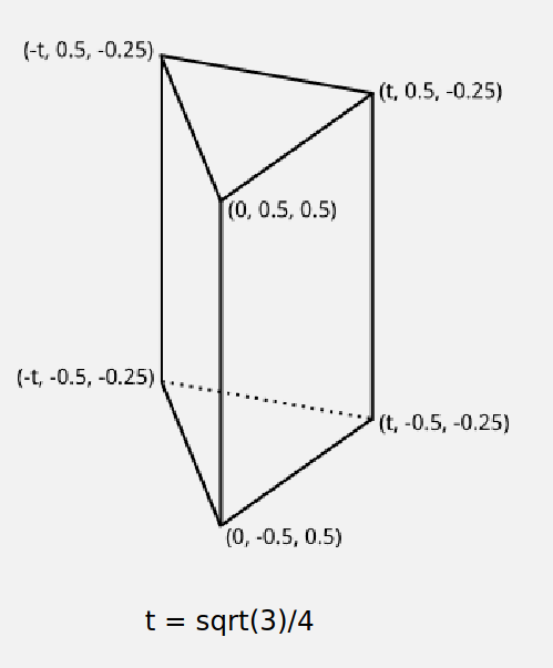
Locate the TODO comments in getModel and fill in the case for the prism. Return an object in the same format as the other IFS objects we've been working with. (Including vertex normals is necessary for lighting, but optional for this part — you only need to define vertex positions, texture coordinates, and the faces.) See below for more details on this.
The geometry for the teapot and other shapes is defined as a JavaScript object in the following form:
	{
	  vertexPositions: ...,
	  vertexNormals: ...,
	  vertexTextureCoords: ...,
	  indices: ...
	}
The ... is a Float32Array for everything but indices, which is a Uint16Array. See the teapot model for an example.
Note that these are defined as triangular meshes — every face is a triangle, so the faces can be given as a 1D list of vertices with every three vertices taken to be a face.
You'll need to define all four properties, but you can define vertexNormals as an empty Float32Array (new Float32Array([])). Lighting won't work, but texture-only should. (Leaving out the vertexNormals property entirely will likely break everything.)
For the prism, wrap the texture once around the sides, so that 1/3 of the texture is used on each side and the edges line up. You can use any triangle from the texture for the top and bottom of the prism; as a challenge (and for some extra credit), make the triangle line up with one of the edges so that it looks like a flap of texture folded over from one side of the prism and also make the scaling of the texture on the sides of the prism match up with the scaling on the ends.
Keep in mind that while the general goal of the indexed face set representation is to not repeat vertices that are shared by multiple faces, that assumes that all of the properties of the vertex — coordinates but also normals, texture coordinates, etc — are shared by every occurrence of that vertex. If any of your vertices have different texture coordinates (or normals) in different faces, you'll need to repeat them.
If you are defining vertex normals (optional), also keep in mind that the prism is a polyhedron, not a polygonal mesh approximating a smooth surface. You'll want flat shading and thus polygon normals rather than vertex normals.
(There's no part 6b.)
Work with lab6c.html for this section.
The provided lab6c.html uses the texture coordinates defined as part of the model. Your task is to implement two ways of generating texture coordinates — projection onto the xy plane and the "convert point to shape coordinates" approach using a sphere as the shape.
Try out lab6c.html — the "from model" method of texture coordinate generation uses the texture coordinates defined in the model.
Optionally copy over your mix, replace, and/or modulate blends from lab6a.html so you can see the textures with lighting.
Optionally copy over your prism from lab6a.html if you want to generate texture coordinates for it.
Technical notes:
Texture coordinate generation should be done in object coordinates, so you may need to modify what is passed from the vertex shader to the fragment shader in order to have the necessary information in the fragment shader.
You can assume that the object coordinates shapes are centered at the origin and, except for the teapot, have coordinates in the range -0.5 to 0.5.
Projecting onto the xy plane means mapping the x and y components of the OC (x,y,z) point to u and v, respectively. Keep in mind the technical note above — the OC values range from -0.5 to 0.5 while u and v should be in the range 0 to 1.
"Shape coordinates — sphere" means treating the OC (x,y,z) point as if it is a point on a sphere and applying the shrinkwrap method to determine (u,v). The computation:
  u = atan(y,x)/2π + 0.5
  v = asin(z/r)/π + 0.5
where r is the radius of the sphere through (x,y,z) — this is also the distance from (x,y,z) to the origin and you can use the GLSL function distance to compute r. GLSL also has functions atan and asin but it does not define a constant for π — you'll have to use 3.1415927.
Implement the "projection — xy plane" method — locate the TODO for that case in the fragment shader's main and set texcoords to the computed (u,v) coordinates.
Implement the "shape coordinates — sphere" method — locate the TODO for that case in the fragment shader's main and set texcoords to the computed (u,v) coordinates.
Optionally implement the other three methods (projection — cube, cube map shape — normal, and sphere map shape — normal). The slides from class provide a definition for what each of these are, but you'll have to work out the math for yourself. (This gets trickier for the map shape methods since you'll need to compute ray-cube and ray-sphere intersections.)
Work with lab6d.html for this section.
The provided lab6d.html supports applying procedural textures to shapes.
Try out lab6d.html — the 2D and 3D checkerboard and 3D marble textures can be applied to any of the objects (though the scale factor may not be good for the teapot). "Lighting only" also works.
Optionally copy over your mix, replace, and/or modulate blends from lab6a.html so you can see the textures with lighting.
The goal of this section is to gain a (very) introductory understanding of how one can start to build up procedural textures to achieve various effects. You'll modify aspects of the 2D and 3D checkerboard and marble textures from class to better understand how they work, and then create two new textures (stripes and wood).
Technical notes:
When experimenting with or implementing a particular texture, it's helpful to change the default selections (object, blend, texture) so that you don't have to keep clicking on what you want every time the live preview reloads. Scroll down to the HTML at the bottom of the file and note that some of the input elements for the radio buttons contain the keyword checked. Move that keyword to the options you want to be selected by default e.g. to make the torus the default object instead of the cube, move checked from the cube element to the torus element.
The provided texture coordinates for the basic object shapes (everything except the teapot) seem to be in the range 0 to 1. For the teapot, the texture coordinates seem to be in the range 0 to 2.
The basic objects displayed in the scene (everything except the teapot) are sized so that their objects coordinates are in the range -0.5 to 0.5. The teapot is not. (Its coordinates have a much bigger range.)
Do the following steps and think about the questions posed, but you don't need to write down answers or turn in anything.
Review the checkerboard2D and checkerboard3D functions in the fragment shader. What's the role of scale? Experiment with changing its value (passed from main).
Review the marble3D function in the fragment shader.
Experiment with changing the value of scale (passed from main).
What's the effect of the noise? Change the 1.5 multiplier to 0.0, then try other values (increase slowly from 0 for a bit, then try a range of values including some larger ones).
Comment out the t += 1.5*snoise(v) line for the next two steps.
What's the effect of the sqrt? Try using just value instead of sqrt(value) for the final color. Restore the sqrt when you are done.
What's going on with the value computed for t? Try just v.x, just v.y, and just v.z as well as shapes other than just the cube. Then try combinations e.g. v.x+v.y. Then add in the 2.0 and 3.0 multipliers one at a time. Restore the original v.x+2.0*v.y+3.0*v.z formula when you are done.
Restore the t += 1.5*snoise(v) line so the marble texture is back to its original version.
|
Stripes alternate between two colors. This can be viewed as a blend of two colors where the blend amount is either 0 or 1, which gives a design strategy for a stripes texture — figure out a function that yields blend amounts that alternate between 0 and 1. The stripes2D function in the fragment shader contains a skeleton implementation for a 2D stripes texture which sets up this strategy. Your task is to replace the hardcoded 0.5 value for blend to produce stripes as noted by the TODO comment — follow the steps below. Feel free to change the two colors defined and/or n.
|

|
|
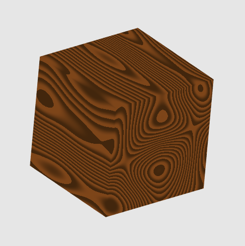
A wood texture also involves gradients between two colors. The wood3D function in the fragment shader contains a skeleton implementation for a blending of two colors, similar to the starting point for the stripes. As with stripes, your task is to replace the hardcoded 0.5 value for blend to produce a wood grain texture as noted by the TODO comment — follow the steps below. Feel free to change the two colors defined, though keeping some sort of shades of brown will help the texture look more like wood.
|
|
There are several optional (extra credit!) extensions possible —
With the wood texture it's also possible to perturb the object coordinates using noise instead of (or in addition to) perturbing the distance computed. Try this out — if you find an especially nice wood-like texture, keep it! (Otherwise go back to the version from the steps above.)
Implement your own 2D and/or 3D textures as the "user defined" options. This is meant to be a chance to experiment rather than a research project — build up your own textures rather than looking up something from another source.
Copy over the support for texture transforms from lab6a.html, and supply appropriate texture transforms so that the textures work well with all of the shapes (including the teapot).