| CPSC 424 | Computer Graphics | Fall 2025 |
This lab continues with adding elements of photorealism to our basic lighting model and deals with simulating rough textured surfaces (bump mapping), reflection and refraction (environment mapping), and shadows (shadow mapping).
This is an individual lab. You may get technical help from others, but the effort and ideas that go into producing solutions should be yours.
![]() You may use AI as outlined in
the Use of AI policy —
Copilot's inline coding suggestions, explain, fix, review and
comment features but not code generation from English prompts.
Also:
You may use AI as outlined in
the Use of AI policy —
Copilot's inline coding suggestions, explain, fix, review and
comment features but not code generation from English prompts.
Also:
Hand in your work by copying your ~/cs424/lab7 folder into your handin folder (/classes/cs424/handin/username, where username is your username).
Check that the result is that your files are contained in /classes/cs424/handin/username/lab7 — if not, fix it!
Copy /classes/cs424/cubemap-textures and its contents into your ~/cs424/workspace directory. Make sure that you end up several folders (each containing the six images making up a cubemap) inside a folder cubemap-textures which is directly contained within workspace.
Copy the contents of /classes/cs424/lib into your ~/cs424/workspace/lib directory. Make sure that you end up (only) with a bunch of files inside ~/cs424/workspace/lib instead of multiple nested lib directories.
Copy the directory /classes/cs424/lab7 and its contents into your ~/cs424/workspace directory. You should end up with a folder lab7 inside your workspace directory, with files inside of it.
Make sure that all of the directories are named exactly as specified and end up at the same (top) level in your workspace directory. This is important so that the relative path names used to access common files remain the same so your program doesn't break when you hand it in.
The cubemap-textures directory you copied contains several sets of images for cubemap textures.
The lib directory contains some new and updated files:
webgl-texture-utils.js contains some additional utility routines for loading cubemap and bumpmap textures from files.
basic-objects-models-tangents.js adds the tangents needed for bump mapping to the basic objects (sphere, etc).
Your best reference sources are the slides from class (which pull out and organize the key points), the examples from class (which put all the pieces together), and the textbook.
Work with bumpmap.html for this section.
The provided code displays a scene with several textured shapes. It also loads a bumpmap texture and initializes a texture object for bump mapping but doesn't do anything further with them. Your task in this part will be to implement bump mapping.
Review bumpmap.html — make sure you understand the organization and recognize and understand the standard WebGL program elements.
Locate where the bump map texture is loaded and the texture object initialized (near the end of initGL). This code has been provided because the structure is a bit complicated due to JavaScript loading files asynchronously. Review the code to make sure you recognize and understand the WebGL elements involved in setting up bump maps that were discussed in class. (loadBumpmapTexture is defined in lib/webgl-texture-utils.js.)
Bump mapping is done in shaders — the JavaScript program just serves to get the data to the shaders for drawing geometry.
The slides from class outline the steps for implementing bump mapping, and the bumpmap demo in section 7.3.4 of the textbook provides a full implementation. (Do "view source" in your web browser to see the code behind the demo.)
Add support for bump mapping to the shaders. The core of this is the computation of the perturbed normal, which is given on slide 74 from Mon 10/6. (Does that go in the vertex shader or the fragment shader?) You will also need to add attributes, uniforms, and/or varying variables.
Update the JavaScript to pass the necessary information to the shaders. Note that the texture object for the bump map is already set up, but you will need to add the rest. Apply different strengths to each row of the shapes — pick values where there's a visible difference in the result.
This is pretty much just a copy-and-paste task, though with adaptation — some elements in the provided code have been arranged somewhat differently from the book's demo, and names may be different. Make sure you understand what each element is doing!
Initially a set of 3x3 convolution matrices were introduced for computing Bu and Bv, but the book's implementation and the code given in class use a simpler set of 1x3 and 3x1 matrices. Does that make a visible difference?
Add the 3x3 matrix implementation to your shaders — add a parameter (similar to u_texture.replace) that allows for runtime selection of which implementation to use rather than replacing the existing computation, and specify different options for the two rows of objects in the scene. Can you see any difference? See slide 72 from Mon 10/6 for the 3x3 convolution matrices to use.
Work with envmap.html for this section.
The provided code displays a scene with several shapes and a user interface with a toggle between normal lighting, reflective, and refractive for the sphere in the middle. It also loads a cubemap and initializes a texture object for the skymap but doesn't do anything further with them. Your task in this part will be to implement environment mapping with dynamic cubemaps.
Review envmap.html — make sure you understand the organization and recognize and understand the standard WebGL program elements.
Locate where the skybox cubemap texture is loaded and the texture object initialized (near the end of initGL). This code has been provided because the structure is a bit complicated due to JavaScript loading files asynchronously. Review the code to make sure you recognize and understand the WebGL elements involved in setting up cubemaps that were discussed in class. (loadTextureCube is defined in lib/webgl-texture-utils.js.)
The slides from class outline the steps for implementing environment mapping with dynamic cubemaps, and the dynamic cubemap demo in section 7.4.4 provides a full implementation. "View source" in your web browser to see the code behind the demo.
Proceed in three steps:
Display the skybox — look for the TODO [skybox] comments and implement those steps. Note that two of the steps (declaring a variable for cubemap texture object and loading the cubemaps) have already been done. The result of this step is that you should see the scene with the skybox surrounding it.
Implement environment mapping with the static cubemap.
Start with reflection — look for the TODO [envmap] comments and implement those steps. The shaders should be the ones for reflective objects.
Add support for refraction: look for the TODO [refraction] comments and implement those steps. When updating the shaders, add a parameter to allow runtime selection of reflection or refraction (similar to what you did to support the two different convolution matrices for bump mapping) as well as a parameter for the index of refraction ratio. Also be sure to do all the necessary updates in the JavaScript program to support new shader parameter(s) even if those spots aren't explicitly marked with TODO. You can hardcode a value for the index of refraction ratio in the JavaScript (don't hardcode it in the shader).
Experiment with different values for the refraction ratio to find something pleasing. (Don't try to relate this ratio to actual index of refraction values. This scheme of refraction via environment mapping is only an approximation, and is only half an approximation at that — the light ray should bend again as it exits the object on the other side.)
The result of this step should be a sphere which correctly reflects or refracts with just the skybox texture — the other shapes in the scene won't be reflected or visible through the spheree.
Generate a dynamic cubemap and use that for the environment mapping instead. Look for the TODO [dynamic] comments and implement those steps. The result should be that the other objects in the scene are now included in the rendering of the sphere.
This is pretty much just a copy-and-paste task, though with adaptation — some elements in the provided code have been arranged somewhat differently from the book's demo, and names may be different. Make sure you understand what each element is doing!
Work with shadows.html for this section.
The provided code displays a scene with lighting and several objects. It also contains shaders for generating a shadow map, but no other support for shadow mapping. Your task in this part will be to add that support.
Review shadows.html:
Observe vshader_shadow and fshader_shadow, the shaders for generating the shadow map — they are very barebones because all that is needed for the shadow map is the depth information for the clip coordinates points.
Note how the two shader programs and all their associated location variables are handled (similar to envmap.html).
Observe the handling in the set* methods — using the same names for the same locations (even if the shader parameters don't have the same name) along with the === undefined or !== undefined check for parameters not shared allows the same set* routines to be used for both shaders.
The slides from class outline the ideas behind shadow mapping. Review those!
Generate the shadow map — implement all of the TODO comments in the JavaScript parts of shadows.html except for the one in the "draw scene" section of draw. See the details below for more information.
Generating a shadow map is very similar to the "render to texture" process discussed in class, except that the shadow map texture is set up to capture depth information rather than color information.
To create a texture object and set it up as a depth buffer:
  shadowMap = gl.createTexture();
  gl.bindTexture(gl.TEXTURE_2D, shadowMap);
  gl.texImage2D(gl.TEXTURE_2D, 0, gl.DEPTH_COMPONENT16,
                SHADOW_MAP_SIZE, SHADOW_MAP_SIZE,
                0, gl.DEPTH_COMPONENT, gl.UNSIGNED_SHORT, null);
  gl.texParameteri(gl.TEXTURE_2D, gl.TEXTURE_MAG_FILTER, gl.NEAREST);
  gl.texParameteri(gl.TEXTURE_2D, gl.TEXTURE_MIN_FILTER, gl.NEAREST);
  gl.texParameteri(gl.TEXTURE_2D, gl.TEXTURE_WRAP_S, gl.CLAMP_TO_EDGE);
  gl.texParameteri(gl.TEXTURE_2D, gl.TEXTURE_WRAP_T, gl.CLAMP_TO_EDGE);
Note that SHADOW_MAP_SIZE is a constant defined earlier in shadows.html. shadowMap should be replaced by whatever you named the shadow map texture object.
Create and bind a framebuffer as in the "render to texture" slides, then attach the shadow map texture object to it as a depth buffer:
  gl.framebufferTexture2D(gl.FRAMEBUFFER, gl.DEPTH_ATTACHMENT, gl.TEXTURE_2D,
                          shadowMap, 0);
It is not necessary to attach a color buffer to the framebuffer.
The "render to texture" slides also show how to make a framebuffer the current framebuffer, set the viewport (use SHADOW_MAP_SIZE for the viewport size), clear the color and depth buffers, and set the current shader program (shader_shadow).
The single light for the provided scene is a directional light with the position lightpos. Set up the viewing, projection, and modeling transforms (i.e. initialize the global variables modelview and projection) as directed in the TODO comment. Note that modelview is an object containing separate model and view transforms — this will be needed in the next step (using the shadow map).
A challenge is knowing whether you have an appropriate view volume — everything that is to generate shadows must be inside the view volume used to generate the shadow map, but what is displayed on the screen is the normal-lighting rendering of the scene. There is a key trick to debugging shaders: while you can't output directly to the console from a shader, you can set gl_FragColor in a way that provides information. See main in fshader_shadow — gl_FragCoord.z will be between 0 and 1, so its value can be used directly as a color value. This will provide two pieces of information — whether the desired geometry is visible inside the view volume and whether there is a good span of z values (avoid making the distance between near and far bigger than necessary). To visualize the shadow map, render it to the screen instead of a separate framebuffer: in draw(), comment out the lines where you set the framebuffer and viewport for the shadow map framebuffer and instead copy in the lines from the "draw scene" section which set up the framebuffer and viewport for normal drawing, then comment out the entire "draw scene" section so that only the shadow map scene is drawn.
Once you have a reasonable-looking shadow map, uncomment the commented things and return to rendering the shadow map to its own framebuffer.
Utilize the shadow map in the lighting computation — implement the TODO comment in the fragment shader and in the "draw scene" section of draw. See the details below for more information.
The slides on shadow mapping outline the steps needed in fshader: transform the point into the light's coordinate system and then only include the contribution from that light (diffuse and specular terms) if the depth of the transformed point is no greater than the depth in the shadow map i.e. the point is closer to the light than anything else and so isn't in shadow.
These computations need two pieces of information: the light's viewing-and-projection matrix (mat4) and the shadow map texture (sampler2D). Since these are properties of a light, add lightMatrix and shadowMap to the LightProperties struct in both vertex and fragment shaders.
Sampling the texture to determine if a point is shadowed is a per-pixel task, but transforming the OC point to the light's coordinate system can be done by the vertex shader:
vec4 lightcoords = u_light.lightMatrix * u_view.model * coords; // coords is EC point
Light coordinates are within the canonical view volume for the light, meaning that the coordinates are in the range [-1,1]. The shadow map is a depth texture, however, and both texture coordinates and depth values are in the range [0,1]. The vertex shader should perform this additional standardization before passing the result along to the fragment shader. Add a varying vec3 variable v_texcoords to both shaders and initialize it as follows:
v_texcoords = (lightcoords.xyz/lightcoords.w+1.0)/2.0; // perspective divide + map to [0,1] for texture lookup and depth comparison
The fragment shader needs to sample the shadow map at v_texcoords.xy and compare that to the depth of the current point (v_texcoords.z):
  float shadow = 1.0;    // no shadow
  float depth = texture2D(u_light.shadowMap, v_texcoords.xy).r;
  if ( v_texcoords.z > depth ) {
    shadow = 0.0;       // in shadow
  }
shadow is then a multiplier applied to the direct lighting terms of the lighting equation (diffuse and specular, not ambient).
Finally, handle the JavaScript side — initialize the appropriate location variables for the light matrix and shadow map shader parameters and make sure values get set so the necessary information is actually passed to the shaders. Also be sure to implement the TODO comment in the "draw scene" section of draw() to bind the shadow map texture object to a texture unit.

Running the program now should result in shadows being visible...but you'll probably also see a strong moiré pattern known as shadow acne.
Shadow acne results from floating-point rounding errors and limited resolution of the texels in the shadow map and the depth values in the depth buffer. When the point being checked is the surface point closest to the light that generated the depth value in the shadow map, the computed LC z coordinate may end up being slightly larger than the stored depth, resulting in an incorrect shadow.
One way to lessen the effect of shadow acne is to apply a small depth bias so that a point is only considered shadowed if it is definitely behind the frontmost surface in the depth map.
Add depth bias:
  float shadow = 1.0;    // no shadow
  float depth = texture2D(u_light.shadowMap, v_texcoords.xy).r;
  if ( v_texcoords.z > depth + bias ) {
    shadow = 0.0;       // in shadow
  }
Experiment with different values for bias to find a pleasing effect — remember than depth values are in the range [0,1] and the goal is to deal with precision errors, so the bias should generally be quite small.
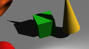
Too big of a bias can result in an effect known as peter panning, where a shadow can appear detached from the object casting it. In the picture, the green cube is sitting directly on the gray surface but there's a gap between the cube's lower corner and its shadow.
In a scene with solid objects, one strategy that can help with peter panning is to render the shadow map using only back faces — then a point on a front face is unlikely to have a greater depth than what is stored in the shadow map so the bias can be reduced without creating shadow acne.
Experiment with different values for bias — make it large enough so that you can see the peter panning effect.
Try the culling trick: enable culling with gl.enable(gl.CULL_FACE) early in draw(), then cull front faces when generating the shadow map and back faces otherwise:
	    gl.cullFace(gl.FRONT);
            drawScene(shader_shadow);
            gl.cullFace(gl.BACK);
What do you see? If you have much of a depth bias, you may discover a new artifact — non-shadowed regions between the sphere and cube and their shadows. This occurs because the sphere and cube are sitting on the gray floor and faces of each surface overlap.
Try reducing the bias to see the effect on the culling artifact.
Another artifact is blocky edges along the boundaries of shadows. This is due to the resolution of the shadow map and the nature of sampling a texture. One option for addressing this is to increase the size of the shadow map:
Adjust the value of SHADOW_MAP_SIZE — make it smaller to exaggerate the blockiness and larger to smooth things out. Remember to keep the value a power of two! Settle on a value that provided reasonable results without being too large — the tradeoff is the extra memory and computational resources needed to generate and work with large textures.
Another partial fix is percentage-closer filtering (PCF) — the idea is to sample a neighborhood of points in the shadow map and average them, softening the edges of the shadows slightly.
Implement a simple averaging scheme — comment out the current computation of the shadow factor in the fragment shader and replace it with:
        float shadow = 0.0;
        float texelSize = 1.0 / 1024.0;  // use the actual shadow map size!
        for(int x = -1; x <= 1; x++) {
	  for(int y = -1; y <= 1; y++) {
	    float depth = texture2D(u_light.shadowMap, v_texcoords.xy + vec2(x, y) * texelSize).r;
	    shadow += v_texcoords.z > depth+bias ? 0.0 : 1.0;
	  }
	}
	shadow /= 9.0;
Do you notice an improvement? You can also experiment with the size of the area being averaged over — try -2 to 2 or -3 to 3, for example, instead of -1 to 1. Be sure to update the division step to 25.0 or 49.0 accordingly.
Finally:
Settle on a bias amount, whether or not you employ culling, shadow map size, and averaging area that best minimizes shadow acne, peter panning, blocky shadows, and other artifacts.
Optionally add parameters to the shader for the bias, the shadow map size, and whether or not PCF is done so it is easier to configure.