CS 424: Computer Graphics, Fall 2017
Blender Lab 4: The Cycles Renderer
This is our fourth and final lab on Blender, the 3D modeling and animation program. The lab is a brief introduction to using the Cycles renderer. A renderer is a software component that takes all the data that you have constructed to describe a scene, and uses that data to create an image. Blender has several renderers. In previous labs, we have used the "Blender Renderer," which corresponds pretty closely to the type of graphics we have been learning. But Blender also has a more advanced renderer that uses path tracing to create images that are much more physically realistic. (See Section 8.2 for a brief introduction to path tracing; Cycles itself is not covered in the textbook) In fact, someone who is working seriously with Blender these days would probably be using Cycles.
You should start with a copy of cycles.blend, which you can get from /classes/cs424. Double-click the file to open it in blender. The scene shows several objects, but only the plane at the bottom of the scene has been assigned a material. You will spend the lab creating materials for the other objects.
For this lab, the requirement to get full credit is that you be present and working seriously during the lab, and that you show me your work shortly before the end of the lab.
After the end of lab, I will put a copy of my completed file, cycles_complete.blend in /classes/cs424, in case you want to take a look at it.
About Materials and the Node Editor
The file cycles.blend has already been set to use the Cycles Renderer rather than the basic renderer. Cycles doesn't understand the materials used by the Blender Renderer. It has its own more general notion of material, based on shaders. A surface material shader computes a color for each pixel on a the surface of an object.
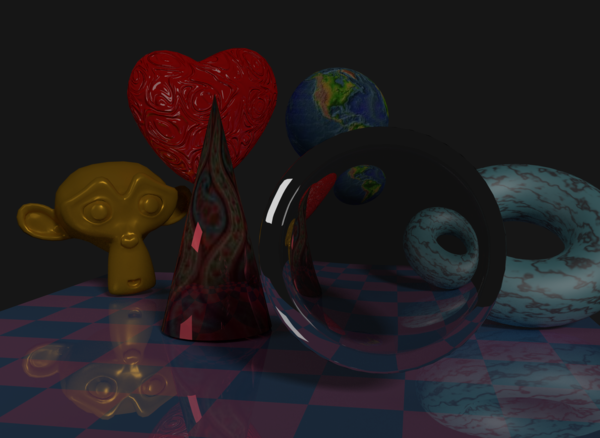
When you open cycles.blend, you'll see the button panel on the right, with the Material Buttons selected. The panel shows the material for the plane that is selected in the view on the left. The material is a shiny pink and light-blue checkerboard, as seen in the Preview area:
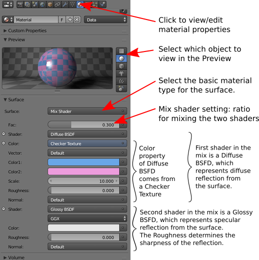
The material is made by "mixing" two simpler shaders, a "Diffuse BSDF" shader that specifies the basic color, and a "Glossy BSDF" shader that adds specular highlights and mirror-like reflection. The diffuse color, in turns, comes from a "Checkers Texture." The material buttons show how the shaders and texture are combined to produce the final material color. However, a more intuitive view of the computation is shown in the Node Editor. To see it, you need to switch the view to a different screen: Find the Screen menu at the top of the Blender window, currently set to "Default." It is just to the right of the "Help" menu. Click the little icon on the left end of the menu, and the list of available screens will pop up. Select the "Node Editor" screen, so that the menu looks like this:
![]()
The Blender window will change to show a Node Editor panel, with two small 3D views of the scene to its left. (Note that screens in Blender are configurable. The Node Editor screen is not a standard part of Blender; I added it to the file cycles.blend. You can convert any panel to a Node Editor view using the View Type popup menu at the lower left corner of the panel.) The Node Editor shows the nodes for the material on the currently selected object, which is still the pink/blue checker material:
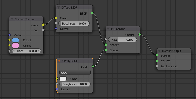
The nodes are arranged in a linked structure that is actually a data-flow diagram. The diagram shows how the final material color is computed as the output of the Mix Shader, which is the final node on the right. The Mix Shader node gets its inputs from a Diffuse BSDF shader node and a Glossy BSDF shader node. The color for the Diffuse shader node comes from a Checker Texture node. This is the same structure that is displayed in the Material Buttons, but the node view is easier to understand and easier to work with.
Most of the nodes have parameters that can be set. For example, the Mix Shader has a numerical parameter named "Fac" that controls how much each of the two input shaders contributes to the mix. You can click the input box and type a new value, or can change the value by dragging left/right on the input box. The Checkers texture has two color parameters. Click on a color if you want to change it. The Glossy shader has a numerical parameter named "roughness" that determines how sharp the specular reflection will be; a value of zero gives perfectly sharp, mirror-like reflections. The Diffuse shader has a color parameter, but it is currently taking its value as input from the Checkers texture. You can disconnect the input by clicking in the little yellow "Color" disk in the Diffuse BSDF node, and dragging away from the disk; when the input is not connected to another node, you see the usual Color swatch in the Diffuse shader node. To reconnect, drag from the yellow Color output of the Checkers texture to the yellow Color input of the Diffuse shader.
You should play with some of the material nodes for the base of the stage! But first, so that you can see the result, you should change the "Viewport Shading" popup menu to "Rendered" for the small 3D view in the lower right of the Blender window. To do that, find the Viewport Shading popup menu at the bottom of the 3D pane (just to the right of "Object Menu"):
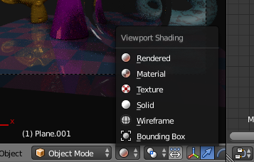
Click the menu icon and select "Rendered" from the popup menu. You will see a somewhat rough rendered view of the scene that will be re-rendered every time you make a change to the materials or other properties of the scene. If you want to go back to the standard view, select "Object" from the same menu. You can do the same thing with the larger view in the "Default" screen, if you want to see a rendered view there.
Your first materials
Your job for the rest of the lab is to apply materials to the other objects in the scene. Start with something simple but still neat... Select the large round object at the front of the screen. (Right-click an object in any 3D view to select it.) Since that object has not been assigned a material, the material button pane will just show a "New" button:
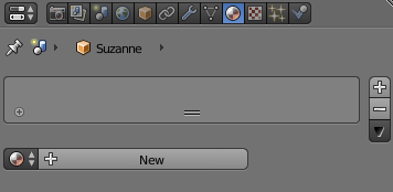
Click the "New" button. A new material that simply uses a Diffuse shader will be added to the material. Change the shader to a "Glass BSDF" shader: Just click the button that says "Diffuse BSDF" in the button pane to get a popup menu of available shaders, and select "Glass BSDF: from the menu. Change the value of the IOR property of the Glass shader to 0.5. The object should look like it's made of glass in the rendered view of the scene.
Another simple type of shader is an "Emission" shader. An Emission shader makes an object emit light that actually illuminates other objects in the scene. Make the small plane at the upper left of the scene into an emitter of light. (Right click to select it, click the "New" button in the material button pane, and change the type of shader to "Emission".) You might want to experiment with the color or strength of the light emitted by the plane. You could also move or resize the plane to get the kind of illumination that you want.
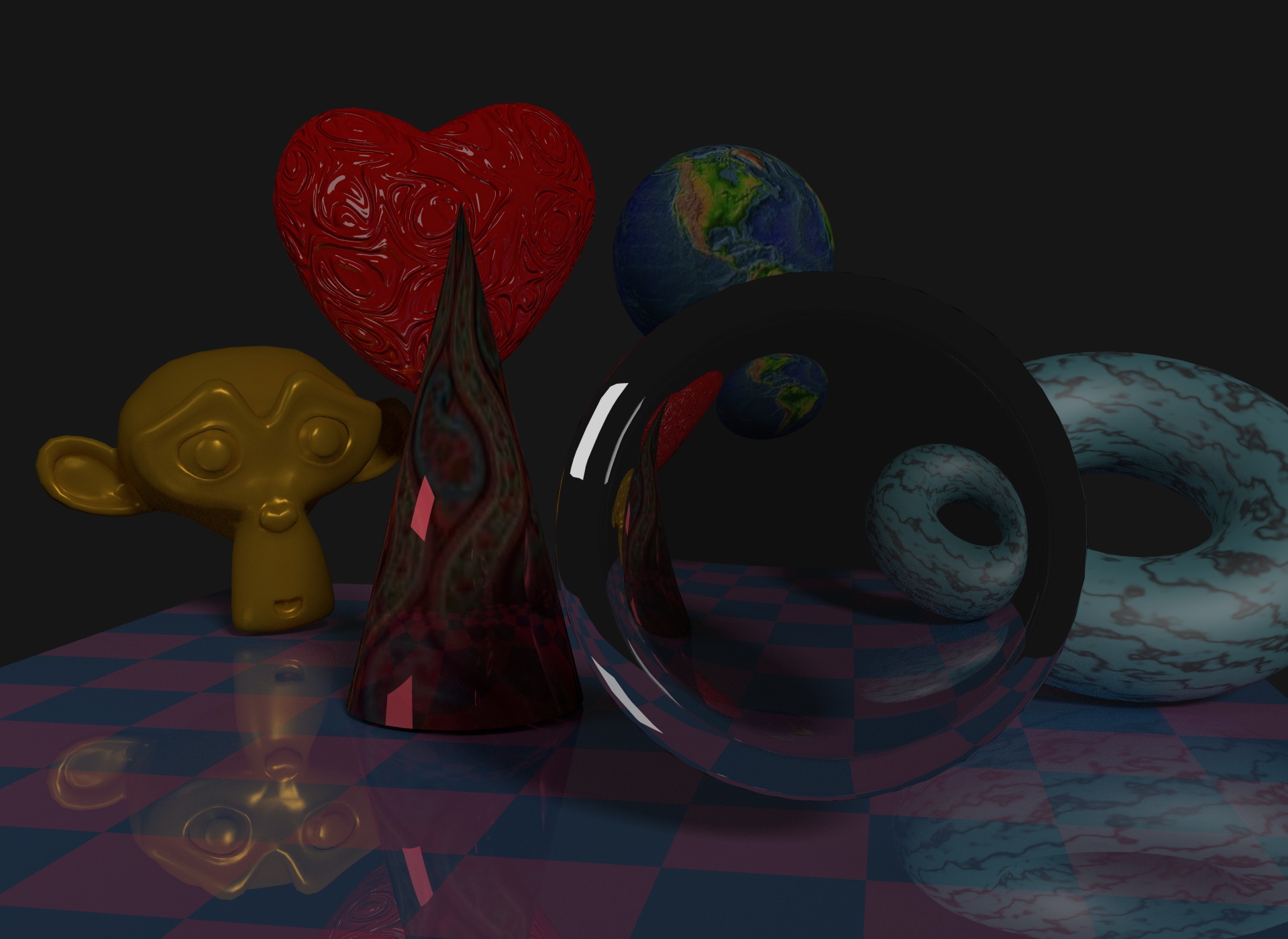
You will create more complex materials for the other objects. Here is what my final scene looks like:
There is also a prettier, larger version. (You might want to make a final rendered image of your own version of the scene. Remember that to render an image, you can press the F12 key. You can interrupt a render with the Escape key. To save the rendered image while it is visible, use the F3 key. To hide the rendered image, press F11. For the rendered image, Cycles has been set to use 100 sampled paths per pixel, instead of the 10 that are used for the preview rendered image in the Blender window; this setting can be found in the Render buttons.)
The basic diffuse+glossy material
As with the older Blender Renderer, a common simple material in Cycles combines diffuse and specular reflection. (A difference is that a specularly reflective object in Cycles will reflect other objects as well as lights.) Such a material can be made by using a Mix Shader to combine the outputs of a Diffuse BSDF Shader and a Glossy BSDF Shader. Here, for example, are the nodes that I used for the monkey head in my version of the scene:
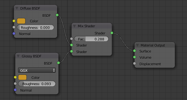
To do something similar... Right-click the monkey head to select it. Click "New" in the material button pane. Add a Mix Shader to the Node Editor: You can either use the "Add" menu at the bottom of the node editor pane, or you can place the mouse cursor over the node editor pane and hit SHIFT-A to pop up the same menu. Select "Mix Shader" from the "Shader" submenu. Drag the Mix Shader node into position between the Diffuse BSDF node and the Material Output node—if you simply drag it into position, Blender will adjust the positions of the other nodes and will change the links between the nodes appropriately. Next, add a "Glossy BSDF" node, and connect its output to the second input of the Mix Shader node. This sets up the correct structure for the material.
Now you can adjust the color parameters in the Diffuse and Glossy shaders, the roughness parameter in the Glossy shader, and the fac parameter in the Mix shader to get the effect that you want. For a highly reflective metal look, set the roughness to zero and make the diffuse color the same as the glossy color. For a more plastic look, the glossy color should be white.
Note that in addition to dragging individual nodes with the left mouse button, you can drag the entire set of nodes with the middle mouse button. Also, you can scale the view by rolling the scroll wheel (which is also the middle mouse button).
Using a displacement map
You've probably noticed that a Material Output node has three inputs: Surface, Volume, and Displacement. So far, we've only used the Surface input, which computes colors for points on the surface of an object. The Volume input allows you to set properties of the interior of an object; it can be used for things like smoke, but I haven't learned how to use it. The Displacement input lets you apply a displacement map to the surface, to make the surface look bumpy. In my version, I applied a displacement map to the heart. To do that, I simply connected the Fac output of a Texture node to the Displacement input of the Material Output node:
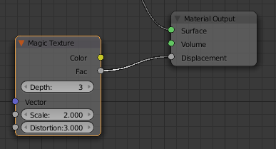
The Fac output from a texture is a scalar (a number) that gives the grayscale value of the texture. Scalar inputs and outputs are represented by gray-colored disks. As a general rule, an output from a node should be connected to an input of the same color, representing the same kind of data.
Using an image texture
The Color output from a texture node can be connected to the Color input of a Diffuse shader to apply a texture to an object. In my scene, I applied Image Textures to the Diffuse colors of the sphere and cone. Here is my setup for the sphere:
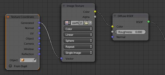
(I also had to rotate the sphere to get it to show North America.)
After adding the Image Texture node, I clicked an "Open" button in that node to select the image that I wanted to use for the texture. Note that in addition to connecting the color output of the Image Texture node to the color input of the Diffuse shader node, I changed the third popup menu in the Image Texture node from "Flat" to "Sphere". This popup controls "generated" texture coordinates, which are computed by Blender rather than assigned explicitly by the user. Spherical generated texture coordinates are appropriate for wrapping an image around a sphere. However, to get the rendered image to actually use the generated coordinates, I found that I had to add a Texture Coordinate node and connect its "Generated" output to the "Vector" input of the Image Texture node. (You can find "Texture Coordinate" at the top of the "Input" submenu of the "Add" menu.)
Using a procedural marble texture
My last example is a little more complex. I always liked the marble procedural texture of the Blender renderer. Cycles doesn't have a marble texture as such, but it has a "Wave Texture" that can be used to generate marble and wood textures, with the appropriate parameters. Here is how I computed the diffuse color of the torus in my version of the scene:
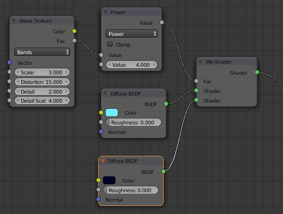
The diffuse color for the marble texture is created by mixing a light cyan diffuse color with a very dark blue diffuse color. The "Fac" input of the Mix Shader node comes from a Wave Texture node, with parameters that I adjusted experimentally to produce a texture that I liked. The "Fac" value goes through a "Power" node, which computes the fourth power of the value; this is done to make the dark bands in the marble much sharper than they would be without the Power node. To make the Power node, I selected "Math" from the "Converter" submenu of the "Add" menu, and changed the popup menu in the resulting node from "Add" to "Power". The effect of using a texture for the Fac input of the Mix Shader is to make the ratio of dark blue to light cyan vary from point to point on the surface.
(If you want to learn more about Cycles shaders, you might take a look at Blender Guru's Shader Encyclopedia. Also, his YouTube tutorials on Blender seem to be pretty good in general.)