CPSC 220, Fall 2012
Lab 7: Memory Circuits
For this lab, you will work with the LogiSim program that you first used in Lab 2. To run LogiSim, you can right-click the icon for logisim.jar in /classes/cs220 and select "Open With OpenJDK Java 6 Runtime". Alternatively, you can start it from the command line with the command java -jar /classes/cs220/logisim.jar.
You will create a series of four circuits. You should create all the circuits in the same file, using the "Add Circuit" command in the "Project" menu to start building each circuit. Save your file under the name lab7.circ. I suggest that you save your file often as you work (and maybe even make extra copies of the file, as you complete parts of the lab).
The lab is due next Tuesday. To submit it, copy your lab7.circ file into your homework folder in /classes/cs220/homework.
This is an individual lab. You should do the work on your own and turn in your own copy of lab7.circ. For the first three exercises, you should use only basic gates, not the more sophisticated circuits that LogiSim makes available. For the fourth exercise, you can use LogiSim components as noted.
Circuit #1: Clocked Latch
The first exercise is to make a clocked latch. This basic circuit has two inputs, data-in and clock. It has one output, data-out. The operation is this: As long as clock is ON, the value of data-out is that same as data-in. When the clock input is OFF, data-out does not change. Basically, the circuit stores the value that is on the input wire at the time that the clock input is turned off.
To build the circuit, start with a basic set-reset circuit. We looked at two ways to make such a circuit in class. Either one should work. For example, use two cross-linked NOR gates:
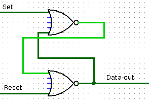
Add some extra circuitry to make sure that set is only turned on when both data-in and clock are on. And reset should be on only when data-in is off and clock is on.
Note carefully: You are not really using a clock -- at least not yet! You are providing an input that could be attached to a clock. However, you will turn the clock input on and off by hand. The clock input is essentially what I called load in class.
Circuit #2: Flip-Flop
Add a new circuit named flip-flop. This circuit also has data-in and clock inputs and a data-out output, but now the output can only change on the falling edge of the clock cycle, that is, at the moment that the clock is turned off.
The circuit is very simple to build, as we saw in class. (Add two copies of your clocked latch circuit, one to be the "master" and one to be the "slave." The master's output connects to the slave's input. The flip-flop's data-in connects to the data-in of the master, while the flip-flop's data-out connects to the data-out of the slave. The flip-flop's clock input connects directly to one of the two latches, and through a NOT gate to the other. Where you put the NOT gate determines whether the flip-flop loads on the rising clock edge or the falling clock edge.)
Circuit #3: Register
Next, build a register. A register has a multi-bit data-in input and a multibit data-out output. It has a one-bit clock input. It can be built using one flip-flop for each bit in the input/output values.
Add a new circuit to your project named register, and construct an 8-bit register. (You might make it 16-bit, if you have the inclination.)
Circuit #4: Simple Add-Accumulator
For the last exercise of the lab, add another circuit named add-accumulator. The circuit will use one register, from Exercise 3, as an accumulator. In this case, the only arithmetic operation permitted on the accumulator is to add a number to it. But you will also need a way to store a zero into the accumulator to get things started.
This means that the circuit will need two control wires, one to load zero into the register and one to perform an addition. Here is a picture of my circuit:
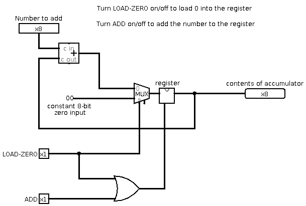
For this exercise, you can use an Adder, a Multiplexor, and a Constant from LogiSim's predefined components. (Find the Constant under "Wiring".)
Extra Ideas
Here are a couple of other things you might do, the first for fun only and second for a little extra credit.
First, use the circuit from Exercise 4 as the basis for a Counter. Hook the data input to an 8-bit constant that always has the value 1. Hook the ADD input up to a clock. You still need a LOAD-ZERO input. To make the clock run, you have to turn on the "Ticks Enabled" option in the "Simulate" menu. For the circuit to work, you will have to start it off by loading zero into the accumulator.
Second, you could make a multi-function accumulator. Instead of just doing addition, it should be able to do addition, subtraction, multiplication, and division. There should still be just one numerical input. And there should be control wires that tell the circuit to perform the various operations.