Section B.1
Blender Basics
Blender has a unique interface, which is consistent across Windows, MacOS, and Linux. It works best with a fairly large display and a three-button mouse. The scroll wheel on most mice works as the third mouse button. A numeric keypad is also useful. Recent versions of Blender have made almost all of its functionality usable with just a left mouse button and basic keyboard, but knowing the shortcuts can still make it easier to work efficiently.
This section discusses how some fundamental aspects of 3D graphics work in Blender, including geometric objects, transformations, light, material, and textures. See Section 1.2 for a basic introduction to these concepts, if you have not already read the relevant chapters of the book.
When Blender starts for the first time, you have a chance to select some customizations. I will assume that you are using the defaults, which include using the left mouse button for selecting things.
B.1.1 The 3D View
The Blender window is divided into non-overlapping sections, which are called "areas." Each area contains an "editor." Any area can be changed to show any editor, using the menu shown at the top left of the area in the illustration below. You can drag a corner of an area vertically or horizontally to split an area in two, or to join two neighboring areas into one. (Or right-click the dividing line between two areas and select a "Split" or "Join" command from the popup menu.)
Areas are in turn divided into "regions." If you have not customized the layout, the central area of the window is a large "3D View" editor that shows a view of the 3D world that you are working in. At startup, it contains a simple default scene. Here's what it looks like, much reduced from its typical size, with annotations on some of its contents:
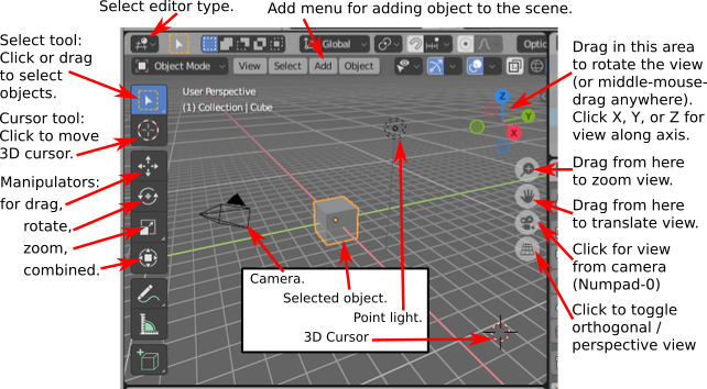
What you see in the 3D view is not what you will see when you make a rendered image of the scene, and the image won't be made from the same point of view. The only thing in the above 3D View that would be visible in the rendered scene is the cube. The camera represents the point of view from which a rendered image will be made. The point light provides illumination for the scene. The other things in the 3D View are there to help you edit the scene or to help you to understand what you are seeing
You can show and hide various parts of the 3D view. For example, pressing the "t" key will toggle the visibility of the toolbar on the left. And the "n" key will toggle a control panel that appears on the right (not shown in the illustration). That panel, for example, lets you enter the position, scale, and rotation of the selected object numerically.
Important Note: In Blender, key presses are sent to the editor that contains the mouse cursor, except when typing into a text input box. This means that the mouse cursor must be in the 3D View for key presses to be sent to that editor. When pressing a key doesn't seem to do what you expect, check the position of the mouse cursor!
You can change the view of the world that you see in the 3D View by clicking or dragging on the controls along the right edge of the 3D View, as shown in the above illustration. But there are also other ways to control the view. Rolling your mouse's scroll wheel while the mouse is over the 3D view will zoom the view in or out. Dragging with the middle mouse button (which usually means pressing and holding down the scroll wheel while dragging) will rotate the view. Shift-dragging with the middle mouse button will translate the view. And the number keys on a keyboard's numpad will affect the view: 1, 3, 7, and 9 select views along the coordinate axes; 2, 4, 6, and 8 rotate the view; 0 selects the view from the camera; and 5 toggles between perspective and orthographic projections. Also, Numpad-Period will zoom in on the selected object or objects. (If using the Numpad, make sure that NumLock is enabled on your keyboard.)
Two other keyboard tricks: If you get lost in the 3D view, just hit the "Home" key, which will bring all objects into view. And if you want to clear away visual clutter so that you can just work on one or a few objects, select the object or objects that you want to work on, and hit the "/" key; the view will zoom in on the selection, and other objects will be hidden. Hit the "/" key again to return to the usual view.
The toolbar at the left edge of the 3D View determines how the left mouse button is used. The default tool is the Select Tool: Click an object to select it, or click and drag to draw a box and select all the objects that intersect the box. Hold down the shift key while selecting to add to the current selection.
Note that the area on the top right of the Blender window contains a scene graph view of the current scene (called an "Outliner" editor in Blender). You can also select objects by clicking on their names in the scene graph view. This can be convenient when the object that you want to select is hidden in the 3D View.
When using the second tool, the Cursor Tool, you can click to set the position of the 3D cursor. You can also set its position by shift-right-clicking with any tool. The 3D cursor is discussed later in this section.
The next four tools can also be used for selecting objects, but they add "manipulators" to the selected object or group of objects. Manipulators can be used to transform an object. Here is what the manipulators for translating, rotating, and scaling an object look like on a cube:
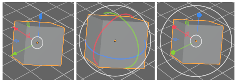
For example, using the translation manipulator, you can drag one of the arrowheads to translate the object in the direction of one of the coordinate axes, or you can drag the white circle to translate the object in the plane of the 3D View. As with most Blender interface elements, you can hover your mouse over any part of a manipulator to see what it does.
But if you are comfortable with keyboard shortcuts, there are other ways to transform objects, without changing the tool that you are using. Select the object or objects you want to transform, then apply the transformation as follows:
- Press the "G" key. (G stands for "grab".) Move the mouse without holding down any mouse button. You can move the object in the plane of the screen only. Click with the left mouse button to finish. Click with the right mouse button to abort. (Hitting return will also finish; hitting escape will also abort.) After hitting the "G" key, you can hit "X", "Y", or "Z" to constrain motion to one axis. Note in particular that you cannot simply click-and-drag an object to move it!
- Press the "S" key. Without holding down any mouse key, move the mouse towards or away from the object to change its size. The size changes in all three dimensions. End the operation in the same way as for the "G" key. After hitting "S", you can hit "X", "Y", or "Z" to scale the object in the direction of one axis only, or hit Shift-X, -Y, or -Z to scale in the two directions perpendicular to the axis.
- Press the "R" key. Without holding down any mouse key, move the mouse to rotate the object around a line perpendicular to the screen. Click with the left mouse button to finish. End the operation in the same way as for the "G" key. If you hit "R" a second time, you can freely rotate the object. Or, after hitting "R", you can hit "X", "Y", or "Z" to rotate the object about the specified axis.
You can get yourself real confused if you don't remember to press the left or right mouse button to complete a transformation operation. You can't do anything else until the operation is completed.
Whether rotating, scaling, or translating, you can hold the Control key down to limit the changes, such as to integral amounts while translating or to multiples of ten degrees while rotating. Also, you can use the arrow keys to make small adjustments.
All these operations can be applied to the camera, just as they are applied to any other object. You can move and rotate the camera to get the view of the world that you want to see when you render an image. You can even apply transformations to the camera while in the camera view (Numpad 0), as long as the camera is the selected object. This can be a good way to get the exact view that you want for the rendered image.
B.1.2 Adding Objects to the Scene
Changing the view does not modify the contents of the world. To do that, you need editing operations such as adding objects to the world. This is where the 3D cursor comes in. The 3D cursor is labeled in the above image of the 3D View editor. A newly added object is always added to the world at the position of the 3D cursor. (You might prefer to just leave the 3D cursor at the origin and move objects into position after you add them.)
You must position the 3D cursor before adding the object. You can do that by shift-right-clicking in the 3D View. Or, select the Cursor Tool in the toolbar on the left edge of the 3D View, and use left-click to position the 3D cursor. The 3D cursor exists in three-dimensional space. You can't tell where it is by looking at the world from just one point of view. Typically, you would check the position of the 3D cursor from several viewpoints by rotating the view or by using the Numpad 1, 3, and 7 keys to switch between views.
Another way to position the 3D cursor is with the "Snap" menu, which you can call up by pressing SHIFT-S while the mouse cursor is in the 3D Vew window. (Remember that the mouse must be in the 3D View for keystrokes to be sent to that editor.) This is one of Blender's strange circular menus that pops up at the position of the mouse cursor—just move the cursor towards one of the options to select it, and press the left mouse button. You can also find a more normal Snap menu as a submenu in the popup menu that you get by right-clicking the 3D View. The Snap menu contains commands for positioning the cursor as well as for positioning objects. For example, use "Cursor To World Origin" to move the 3D cursor to the point (0,0,0).
Once you have the 3D cursor in position, use the "Add" menu to add an object to the world. You can pop up the Add menu at the mouse position by hitting Shift-A, or you can find it in the header at the top the 3D View. The Add menu has submenus for adding several types of objects. I suggest that you stick with mesh objects at first. (A mesh is a surface made up of polygons or a curve made up of line segments.) Various mesh objects are available in the "Mesh" submenu of the Add menu. For example, A UVSphere is a sphere divided into segments by lines of latitude and longitude. An ICOSphere is divided into triangles. A Plane is actually just a rectangle. (When you first start Blender, the object in the default scene is a mesh Cube.)
When adding certain types of objects, there are some options you can change. When you add the object, a panel containing these options appears in the lower left region of the 3D View. You might just see the name of the panel; click it to show the entire panel. The following image shows the panel for a Mesh UVSphere. You can change the number of Segments and Rings, which are the number of subdivisions around the equator of the sphere and the number from the north pole to the south pole. This is the only chance that you will get to set those properties.
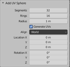
Note that you can set the position and rotation of the newly added object by typing in values. The numerical input widgets in this panel are examples of Blender's funny input buttons. Here's how to use such buttons: You can click the button, type in a value, and press return. You can click the arrows at the ends of the button to increase/decrease the value. Or you can drag the mouse left-to-right or right-to-left on the button to change the value.
Note the "Generate UVs" checkbox. "UV" here refers to texture coordinates for the object. You will need them if you want to apply a texture to the object. ("UV" in this sense has nothing to do with the "UV" in the name "UVSphere," which refers to the u and v parameters used as inputs for a parametric surface.)
To delete the selected object or objects, just hit the "X" key or the Delete key. With the "X" key, you will be asked to confirm the deletion. (Remember that the mouse cursor must be in the 3D window for it to get keyboard commands. (This is the last time I will say this!))
As you modify the world, you can undo most operations by pressing Control-Z. That includes adding, deleting, and editing objects. Control-Shift-Z is the Redo operation.
B.1.3 Edit Mode
Ordinary transformations (and many other operations) are applied to an object as a whole. Sometimes, however, you want to work on the vertices, edges, or faces of an object. For that, you use "edit mode."
To enter Edit Mode for the selected object, press TAB. When in Edit Mode, press TAB to exit Edit Mode. In Edit Mode, you can select individual vertices and groups of vertices. You can select a face by selecting all the vertices of that face. You can select an edge by selecting both vertices of that edge. You can scale, rotate, and translate selected elements in the usual way, with the S, R, and G keys, or using a manipulator. You can delete things with the X key. Right-clicking will pop up a large menu of actions that you can take on the selected elements.
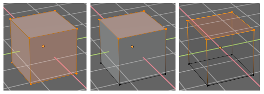
In Edit Mode, selected vertices and faces are orange. The picture on the left below shows a cube in edit mode with all vertices selected. In the second picture, only the vertices of the top face are selected. In can be easier to work in Edit Mode using a "wireframe" view instead of the default "solid" view. Hit the "Z" key to bring up a circular menu of possible views, and select "wireframe"; the default view is "Solid." The third picture shows the cube as a wireframe.
Selection of vertices in Edit mode works in the same way as the seletion of objects in the usual "Object" mode. You can also hit the "A" key to select all vertices. ALT-A (or Option-A on a Mac) will deselect all vertices. When you first enter Edit Mode for a mesh object, all of its vertices are selected. It can be easier to select sets of vertices in wireframe mode. You might have to change the point of view several times while selecting the vertices and performing operations on them.
There are a lot of things you can't do in Edit Mode, so don't forget that you have to press the TAB key to get out of that mode!
By the way, the "Z" key can be used outside of Edit Mode to select how objects are rendered in the 3D View. And "A" and "ALT-A" can be used outside of Edit Mode for selecting sets of objects.
B.1.4 Light, Material, and Texture
We have seen that the "Z" key can be used to select how objects are rendered in the 3D View. There is also a set of four small buttons in the header that can be used to select the view style. In the default "Solid" view and the "Wireframe" view, lighting and material don't affect what you see. The "Material Preview" view, will show objects' materials, but not all lighting effects. The "Rendered" view applies lighting as well.
There is already one point light in the default scene (plus a background that adds something like ambient light). You can select and transform a light just like any other object. An easy way to be sure of lighting all visible objects is to place a light at the position of the camera. You can add additional lights, using the "Light" submenu in the "Add" menu. You will probably need to add several lights to light your scene well.
There are several kinds of light in the "light" submenu. A "Point" light gives off light in all directions. The light in the initial scene is a point light. A "Sun" is a directional light that shines in parallel rays from some direction, indicated by a line drawn from the light position in the 3D view. A "Spot" is a spotlight that gives off a cone of light. You need to aim a sun or spotlight at the objects you want to illuminate. You will see a yellow dot that you can drag to change the direction, or you can apply a rotation to the sun or spot in the usual way.
The default color of an object is gray. To change this, you have to add a "material" to the object and set the properties of that material. (The cube in the start-up world has a material; new objects that you add don't.) To work on materials, use the Properties Editor, which you can find in the lower right area of the window. The Properties Editor allows you to set all kinds of properties of objects. Along the left edge, there is a a column of buttons that select which group of properties you want to work on. The buttons that appear depend on what kind of object is currently selected, although some are always present. Here are the buttons that are shown when the selected object is a mesh:
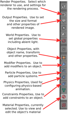
In this picture, the Materials button has been clicked. With the materials button selected, the rest of the editor panel, to the right of the buttons, is filled with controls for setting the material properties of the selected object. Most of the controls don't appear until a material has been added to the object. If there is no material, you will see a "New" button in the Properties Editor. Click the "New" button to add a new material to the object, or click the icon to the left of "New" to select a material that already exists from a menu. The full set of controls will appear. Here's just a part of what you will see:
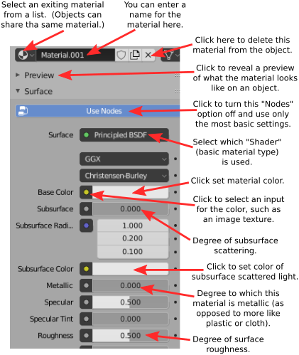
Blender's system for materials is very complex, and the default type of material is the "Principled BSDF," which is itself rather complex. The Principled BSDF tries to implement physically based rendering — using physically realistic materials and lighting rather then approximations like the diffuse and specular reflection properties that are used in OpenGL 1.1. We will just use some of the basic settings of the Principled BSDF. For more information about it and about materials in general, see the Blender manual. We will cover light and materials in a little more detail in Section B.4.
The input labeled "Base Color" is just that, the basic color of the material. If you click it, an RBG color chooser will pop up where you can set the color. Alternatively, you can get the color from a texture, as discussed below.
The next most important input us "Metalic." The input is a number between 0.0 and 1.0 that determines the degree to which the material interacts with light like a metal. Basically, metals are shiny and their specular reflection is the color of the metal. For a non-metal, the specular reflection is white. The "Specular" input determines the amount of specular reflection. Note that there is no specular color as such in the Principled BSDF. (Don't be fooled by "Specular Tint," which is nothing of the sort and which has almost no visible effect that I can see.)
The "Roughness" input tells how rough the surface is. It is similar to OpenGL's shininess property. That is, a rougher surface has larger specular highlights. It also has less sharp reflections.
I have also labeled controls relevant to subsurface scattering. This refers to the fact that light can enter an object, bounce around, and emerge at a different point. It is an important effect for material like skin, milk, and jade, and you can enable it by setting the "Subsurface" control to a value greater than 0.0.
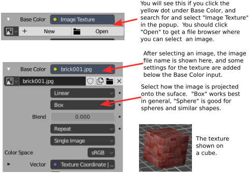
A texture makes the color or some other property of an object vary from point to point. One type of texture copies colors from an image, effectively painting the image on the surface of the object. This is called an image texture. Alternatively, the color can be computed algorithmically from the coordinates of the point. This is called a procedural texture. Blender has both types of texture.
It's not hard to use a texture as the "Base Color" in a Principled BSFD. Click the yellow dot next to "Base Color," and select "Image Texture" from the popup. (Note that most of the items in the popup are not useful here!) Then click "Open" and browse for an image file. You will probably need to set the projection type to "Box" or "Sphere," but otherwise you can accept the default settings. Unfortunately, there is no way to apply a texture transformation, without using more advanced material configuration. Here is what it looks like in the Properties Editor:
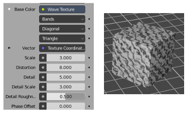
Some of the other entries in the popup are procedural textures. You might try the "Checker," "Voronoi," or "Noise" texture. The "Wave" procedural texture can be used to make marble-like textures, although for now it is limited to grayscale. (See Section B.4 to learn how to add color.) Here is an example, using settings as shown:
B.1.5 Saving Your Work
The 3D window shows positions, sizes, and colors of your objects. To see a fully rendered scene from the point of view of the camera, hit the F12 key. To return to the main window, hit Escape or F11 (or just close the render window). There are also commands in the "Render" menu, at the top of the Blender menu, that do the same things. Remember that you need to render an image to see some aspects of the scene.
When you render an image, the image is created but it is not saved anywhere. To save it, use the "Save" command from the "Image" menu at the top of the render window. The size of the image is set in the Properties Editor, with the "Output" properties selected. The file format can be set there, or in the file browser window when you save the image.
When you save an image—or need to choose a file from the file system for some other reason—you will see the Blender File Browser window. The File Browser, like the rest of Blender, uses a non-standard interface. However, it is not difficult to use. Shortcuts to some directories are listed along the left edge of the window. For saving a file, you should type the file name into the input field at the bottom of the window.
To save your entire Blender session, use the "Save" command in the "File" menu of the main Blender window. A Blender session is stored in a file with the extension ".blend". Opening a .blend file will restore the saved state of the program. If you use the "Save Startup File" command in the "Defaults" submenu of the "File" menu, Blender will save the current state of the program in a .blend file somewhere in your home directory. After that, when you start Blender, it will open that file as the starting point for your session, instead of the usual initial scene. This feature allows you to customize your startup environment.
B.1.6 More Features
We have covered a lot of basic ground about Blender, but before looking at more advanced modeling and animation, there is a little more background information that will be useful...
The Render Engine: A render engine produces a 2D image of a 3D world. Blender has two render engines that can produce high-quality images: Eevee and Cycles. The Eevee renderer is selected by default, but you can select the Cycles renderer in the "Render Engine" menu of the "Render Properties" in the Properties Editor. The selected render engine is used when you make a final render of the scene (F12 key) or when you use the Rendered view style in the 3D View. (There is also a Workbench render engine in the menu, which is used for the other view styles in the 3D View, but it is not meant for producing high-quality images.) Eevee is a fast real-time renderer that uses OpenGL, including a lot of tricks and fancy shader programs for advanced effects. Cycles uses path tracing, which is much slower but can produce highly realistic, physically accurate renderings (see Section 8.2). When you use Cycles for a final rendered image, expect it to take a while. When Cycles is used for the rendered view style in the 3D View, it does less work and produces a "noisier" image. Path tracing is a progressive algorithm, which means that it can produce a fast, noisy image and then add detail to it over time. The longer it runs, the more physically accurate it can be. There are many controls in the Render Properities for configuring the render process. Tuning the process can be difficult, and requires a lot more knowledge than you will get here.
Active Object: When several objects are selected, only one of those objects is "active." If you select several objects by shift-clicking each of them in turn, the active object will be the last one clicked. The active object is shown in a lighter orange outline than the other selected objects. You can shift-click any of the selected objects to make it the active object. When you use the Properties Editor to view or modify properties of an object, it is the active object that you are working with. When you press the Tab key, it is the active object that goes into edit mode.
Parenting: One object can be a "parent" of another. This allows you to create hierarchical models. When you drag, rotate, or scale a parent, all its child objects are transformed as a group along with the parent. But child objects can still have their own transformations within the group. Furthermore, a child of one object can be a parent of another object, so you can do multi-level hierarchical graphics. If you want to group several objects, and there is no obvious parent, you should consider parenting all the objects to an empty object, made with the "Empty" command in the "Add" menu. To create a parent relationship, select two or more objects. The object that you want to be the parent should be the active object; that is, you should shift-click it last. Hit Control-P. You will have to confirm that you want to make a parent; select "Object" from the popup menu. A dotted line will join each child to its parent in the 3D View. To delete a parent relationship, select the child, hit ALT-P, and select "Clear Parent" from the popup menu.
Duplicating: To duplicate the selected object or object, you can hit Shift-D, or find the corresponding command in the menu that you get by right-clicking the 3D View. The copy will be in the exact same place as the original, but will be in "grab" mode so that you can immediately move it away from the original by moving the mouse and clicking after moving it into position.
Smooth Shading: By default, mesh objects have a "faceted" appearance where the polygons that make up the mesh look flat. The effect is called flat shading. Sometimes this is correct, but often you want to use the mesh as an approximation for a smooth object, such as a sphere. In that case you want to use smooth shading instead. To select between flat shading and smooth shading for a mesh object, select the object, right-click in the 3D View, and select "Shade Smooth" or "Shade flat" from the popup menu. Setting a mesh object to use smooth shading does not change the geometry of the object; it just uses different normal vectors (see Subsection 4.1.3).
Naming: In Blender, objects, materials, scenes, etc., all have names. Blender automatically assigns generic names such as "Cube.002" when you create or duplicate an object. Sometimes, you need to know something's name. An example is the "text on curve" feature that will be discussed in the next section. To make it easier to identify an object, you might want to use a more meaningful name. Names are generally displayed in editable boxes. You can just click the box and enter a new name. For objects, the name is displayed in the "Object" properties in the Properties Editor. Click the name there to change it, or find the object in the scene graph view in the upper right area of the Blender window, and double-click the name there to change it.
Screens: A screen in Blender is a customized layout for the Blender window, appropriate to some editing task. In the middle of the menu bar at the top of the Blender window, there is a set of buttons for selecting the current screen. (If you are working in a small window, you might have to middle-mouse-drag the menu bar to see them all.) Here are the default screens:
![]()
We have only been talking about the "Layout" screen, which is the default when Blender starts up. We will look at some of the other screens later, but most of them are for techniques that will not even be mentioned in this textbook. The "+" sign on the right end can be used to add new, customized screens of your own.
Scenes: A "scene" in Blender is its own 3D world. Each scene can contain unique objects, but it is also possible for scenes to share objects. There is a popup menu at the top of the Blender window that you can use to create new scenes and to switch from one scene to another. Scene controls can be found near the right end of the menu bar, next to a set of View Layer controls that I will not discuss:
![]()
Click the icon at the left end of the controls to pop up the menu where you can select a scene. Click the center of the control to enter a new name for the current scene. Click the icon to the right of the name to add a new scene. When you do that, you will get several options in a popup menu: "New" or "Copy Settings" will create an empty scene. "Linked Copy" will create a scene that contains the same objects as the current scene, with the same transforms; if you move an object in one scene, it also moves in the other one. You can then add new objects later that will be in only one of the scenes. You might use this, for example, if you want to set up a common static background world and then make several scenes that show different "actors" doing different things in different scenes, but with the same environment. "Full Copy" makes a new copy of everything in the current scene, so the scenes look the same originally, but really have no shared data in common.