Section B.3
Blender Animation
Blender can be used to create animations and videos. We will look at basic keyframe animation in Blender as well as a couple kinds of animation that can't be done with simple keyframes. At the end of the section, I will explain how to render an animation in Blender.
B.3.1 Keyframe Animation and F-Curves
Blender uses "keyframe animation." That is, you set the value of a property, such as location or scale, in several "key" frames in the animation, and Blender will compute a value for other frames by interpolating between the values for the key frames. Exactly how the interpolation is done is determined by a set of "F-curves," which you can edit to completely control the interpolation (and extrapolation beyond the key frames).
There is Timeline area at the bottom of the default Blender window that contains some information about animations and lets you control them:
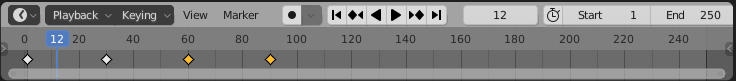
The timeline shows the starting frame number, the end frame, and the current frame of the animation (1, 250, and 12 in the picture). The current frame number specifies the frame that is displayed in the 3D View. These are numerical input buttons that you can edit. To the left of the frame number inputs is a set of playback controls, which run the animation in the 3D View window. You can also start and stop playing the animation by pressing the spacebar. The start and end frames determine the range of frames that are displayed when the animation is played. They also determine what frames will be included when you render an animation. Note that the default 250 frames make a rather short animation when viewed at a typical frame rate of about 30 frames per second.
Below the frame number inputs and playback controls is the timeline itself, with the frame number running along an axis from left to right. The blue tab marks the current frame on the timeline. You can drag the blue tab or click on the timeline to set the current frame. The orange and white diamond shapes mark frames that have been set as key frames for the object that is currently selected in the 3D View (if any). You can drag a diamond to move the key to a different frame, and you can select groups of diamonds. (The orange ones are the ones that are selected). If you right-click the timeline, you get a popup menu; the "Interpolation Mode" submenu can be used to set how interpolation between the selected (orange) keys is computed. (Try the "Elastic" Dynamic Effect.)
To animate an object, you need to enter values for one or more of its properties for at least two key frames. Select the frame number for which you want to enter a key value, by clicking in the timeline or entering the value in the current frame input. Select the object and hit the "I" key to insert a key value for that object in the current frame. (The mouse cursor must be in the 3D View for this to work.) A popup menu will allow you to select the property or properties for which you want to insert key values. For example, to store values for both the current location and the current rotation of the object, select "Location Rotation" from the menu.
After inserting one key frame, change the current frame number, move or rotate or scale the object to the values that you want for the new keyframe, and use the I key again. Then, when you drag the blue tab in the timeline back and forth, you can see how the object animates.
To delete a key from an object, go to the frame from which you want to delete the value, select the object, and hit ALT-I. You will asked to confirm that you want to delete the key.
You can also animate many properties in the Properties Editor panel. For example, to animate the color of the object, set the frame number, point the mouse at the Base Color in the Material Properties, and hit the I key. Change the current frame number and repeat, and so on. You can also insert a key frame by right-clicking a property in the Properties Editor and selecting "Insert Keyframe" from the popup; if a key frame already exists, the popup has an entry for deleting it.
As you get into keyframe animation, you might find that you need more control. You get some control using the Timeline popup menu. But interpolation between keyframes is ultimately controlled by functions called F-curves. You can see the F-curves and edit them in the Graph Editor, which is not shown by default. One way to use it is in the animation screen that you get by clicking the "Animation" button at the top of the Blender window. The bottom of that screen has a "Dope Sheet" that shows keyframe markers for all animated properties. In the Dope Sheet "View" menu, there is a "Toggle Graph Editor" command that will replace the Dope Sheet with a Graph Editor. Alternatively, you can change the editor in any area of the window to a Graph Editor by selecting it from the popup menu in the top-left corner of the area.
The Graph Editor shows F-curves for the object that is selected in the 3D View. Here is the Graph editor showing some F-curves for an animated object that has key frame values for the location and rotation:
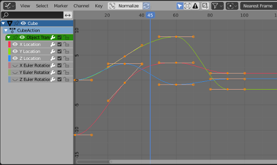
Each curve controls one animated property, plotting the value of the property on the vertical axis against the frame number on the horizontal axis. The curves are Bezier curves by default. In the picture, the Rotation curves have been hidden (by clicking the "eyes" next to the curve names), and the three visible curves and all their Bezier handles have been selected (by hitting the "A" key while the mouse is over the graphs). The dots on the curves mark key frame values. You can select and move them using the "G" Key; hit the "Y" key after the "G" key to force the dot to stay in the same frame. Any changes that you make will immediately affect the 3D View. You can select and move the control points on the Bezier curve handles to change the shape of the curve.
You can change the scale on the graphs using the scroll wheel on the mouse. Or you can control-middle-mouse drag on the graphs; drag vertically to change the vertical scale, horizontally to change the horizontal scale. Without the Control key, dragging the middle mouse button will translate the graphs. An easy way to nicely fit the scale to the graphs is to hit the "Home" key, with the mouse over the graphs.
Let's say that you want an object to rotate through one complete 360-degree rotation about the y-axis as the frame number goes from 1 to 60. You can start with an unrotated object in frame 1 and insert a Rotation keyframe using the I Key. Then move to frame 60. You want the rotation in frame 60 to be 360 degrees about the y-axis, but that means that object will look exactly the same as it did at the beginning! How do you set the value for the rotation keyframe at frame 60? Hit the "N" key with the mouse in the 3D View to reveal the Transform controls, including numerical inputs for the Location, Rotation, and Scale that are applied to the object. You can use those inputs to set the value numerically. Change the Y-rotation value to 360, and then use the I Key to insert the keyframe.
Now, as the frame changes from 1 to 60, you should see the object go through a complete rotation. If you click the playback button starting in frame 0, you will notice that the rotation starts out slow, speeds up, then slows down again at the end. This might be reasonable for an object that starts out at rest, then goes through one rotation, and stops at the end. But suppose you really want a constant speed of rotation? This is a question of interpolation between keyframes. There is also the issue of what happens before the first keyframe and after the last keyframe. That is a question of extrapolation.
To get a constant speed of rotation, you want linear interpolation. To get that, you can select the start and end keys — either on an F-curve, in the Dope Sheet, or in a Timeline — and then choose "Linear" Interpolation Mode, which you can find in the "Key" menu or in the popup menu that you get by right-clicking.
To control extrapolation of the selected properties in the Dope Sheet or Graph Editor, you can use the "Extrapolation Mode" submenu of the "Channel" menu. "Constant" extrapolation, which is the default, means that the property does not change after the last keyframe. "Linear" extrapolation means that the property continues to change after the last keyframe with the same rate of change. "Make Cyclic" means that the entire animation will loop forever after the last keyframe.
For our rotation example, "Make Cyclic" extrapolation will make the full 360-degree rotation repeat forever. Here's what the F-curve for the y-rotation looks like with "Linear"" interpolation and "Make Cyclic" extrapolation:
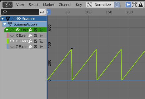
You should have perpetual rotation at a constant speed. Admittedly, this is more complicated than it should be. But hopefully if you work through this exercise, it will give you some idea of how F-curves can be used.
B.3.2 Tracking
Recall that you can "parent" one object to another (Subsection B.1.6). "Tracking"" is a kind of parenting. When one object tracks another, the rotation of the first object is always set so that it faces the object that it is tracking. To set up a tracking relation, click the object that you want to do the tracking, then shift-click the object that you want it to track. Go to the "Track" submenu of the "Object" menu in the 3D View, and select "Damped Track Constraint" or "Track To Constraint." The first, "Damped Track Constraint" seems to work well in general, but "Track To Constraint" seems to work better when it's a camera that's doing the tracking. (You can clear tracking by selecting the object that is doing the tracking and using the "Clear Track" command in the same menu.)
Tracking is in fact a "constraint", and after you set it up you will find it listed in the "Constraint Properties" in the Properties Editor when the tracking object is selected. In the Constraint Properties, you can set which axis of the tracking object points towards the object that is being tracked. (Tracking is only one kind of "constraint." You can use the Constraint controls in the properties editor panel to set and clear various constraints in addition to tracking. "Stretch To" is interesting, and we will look at "Follow Path" later in this section.)
Tracking works especially well for cameras and spotlights. You can make them track moving objects, so that the camera or light is always pointed at the object. This is a place where using an "Empty" object can make sense: You can point the camera or spotlight at a location without having an actual object there, by making it track an Empty. You can move the Empty to direct the spotlight, and by animating the Empty, you can make the camera or spotlight pan across the scene. Or if the camera or light is animated, you can set it to track a stationary Empty to keep it pointed at the same location even as it moves around.
B.3.3 Path Animation
Path animation can be used to move an object along a curve. Any Bezier or NURBS curve will work. For example, you can get circular motion by moving an object along a Bezier circle. For path animation, if you want the motion to be restricted to two dimensions, remember to set the curve to be 2D (Subsection B.2.2).
Curves of type "Path" are often used for path animation. A "Path" in Blender is a kind of NURBS curve for which the endpoints of the curve are constrained to lie at the first and last control point of the curve, which makes it easier to control where the curve begins and ends. To add a path to a scene, use Add / Curve / Path. (The path might be almost invisible, since it is a straight line. I suggest going immediately into Edit Mode by hitting the Tab key, so that you can see it better. You will probably want to be in Edit Mode in any case.) Initially, the path is a straight line with four control points. Recall that you can extend a non-closed path by going into Edit Mode, selecting one of the endpoints, and using control-right-click to add points. You can also add points in the middle of the curve by selecting a pair of consecutive control points and hitting "Subdivide" in the 3D View popup menu. You can close the path by hitting ALT-C key while in Edit Mode. And, of course, you can select control points and move, scale, or rotate them.
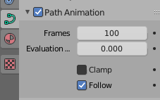
There are two ways to make an object follow a curve. The easiest way treats path animation as a kind of parenting: Click the object, shift-click the curve, hit Control-P, and select "Follow Path" from the popup menu. You will notice that the object does not actually jump onto the curve. To make it do that, select the object that is following the path, go to the "Clear" submenu in the "Object" menu, and select the "Clear Origin" command. You should now have a path animation in which the object moves along the path between frame number 0 and frame number 100, with linear extrapolation after frame 100. To change the number of frames, go to the Object Properties for the curve, in the Properties Editor, and change the value of "Frames" under "Path Animation." Remember that 100 frames is only about 4 seconds! Also, make sure Path Animation is checked there, or you won't see any animation. Checking the "Clamp" checkbox will change the extrapolation mode to constant, so that the object will stop at the end of the path. The "Follow" checkbox makes the object rotate to keep a constant heading as it moves along the curve.
In many cases, this is as much control as you need. But for more control, you can do path animation by using a "Follow Path" constraint. To do that, make sure that you know the name of the curve that you want to use. Select the object that you want to move along the curve, and go to the Constraint Properties in the Properties Editor. Click the "Add Object Constraint" button and select "Follow Path" under the "Relationship" section of the popup menu. This will add the constraint and give you a set of controls for configuring it:
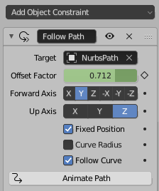
You will need to use the "Target" menu to select the name of the curve that you want the object to follow. To get the object to actually jump onto the curve, you will need to clear it's Location, not its Origin. (Select the object and use ALT-G, or use the "Location" command in the "Clear" submenu of the "Object" menu.)
Use the "Forward Axis" setting in the constraint controls to say which axis of the object points along the curve. You need to check the "Follow Curve" checkbox for that to actually happen. Make sure "Up Axis" is different from "Forward Axis," or you will get strange behavior. Now, if you leave "Fixed Position" unchecked and click "Animate Path," you will get exactly the same kind of path animation that was discussed previously. If instead, however, you check "Fixed Position," you will be able to completely control the animation by animating the "Offset Factor" control, and maybe editing the F-curve for the Offset Factor. A value of the Offset factor between 0.0 and 1.0 specifies distance traveled along the curve as a fraction of the length of the curve. Values less than 0.0 or greater than 1.0 correspond to extrapolated positions beyond the curve or further along the curve if the curve is closed.
For example, insert a keyframe for Offset Factor with value 0.0 at frame 0, and a keyframe value 2.0 at frame 100. The object will traverse the entire curve for the first 50 frames, but then continue moving for the next 50, with values for "Offset Factor" that are greater than 1.0.
The nice thing is that you can start and end the animation at any time. You can choose the interpolation and extrapolation modes. And you can edit the F-curve for full control of the animation along the path. For example, you can vary its speed and even make it move backwards
Note that path animation is not just for visible objects! You can move a Camera or Light along a path. You can combine path animation with tracking. For example, set up a spotlight to track an Empty and move the Empty along a path to tell the spotlight where to point. Or do the same thing with a camera.
B.3.4 Rendering an Animation
There is a command for rendering an animation in Blender's "Render" menu, but you shouldn't simply jump into using it—if you do, it will dump several hundred individual image files with names like 0001.png, 0002.png, ..., somewhere on your hard drive. Before rendering an animation, you should use the Output Properties in the Property Editor to set up the image size, file format, and output location of the rendered animation. Note that's it's not possible to render an animation without saving the result, but you don't get any kind of dialog box when you use the Render Animation command — it just automatically uses the settings in the Output Properties. Here are the relevant properties:
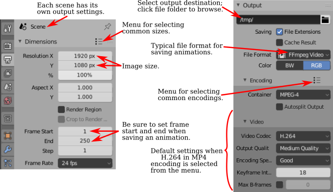
The Output Properties control rendering of individual images as well as animations. The "Resolution" section controls the size of the image that will be produced. You can specify the X and Y dimensions, in pixels, and also a percentage; the stated dimensions are multiplied by the percentage to get the actual image size (presumably to make it easy to make small size test runs). The "Frame Range" duplicates the animation start and end frames from the timeline at the bottom of the Blender window. Note that the "Frame Step" lets you render just a subset of the frames. For example, set it to 2 to render every other frame; again, this can be used to speed things up for test runs.
Also important is a section labeled "Output" near the bottom of the Output Properties, shown on the right in the above image. This section is for controlling the output destination and file format of animations. (It also sets the default file format for single images, but you can also select the file type when you save the rendered image.) When you render an animation, you will see each frame being rendered on the screen. As each frame is rendered, it is saved to disk. You have to set the output destination and format before rendering the animation.
To set the output destination, enter a file path in the box just below the word "Output". If the destination is a directory name ending in a slash, blender will make up the file name, using frame numbers and an appropriate file extension. If there is no slash at the end, then the part after the last slash is the file name, possibly with an added file extension if needed.
The default format for the output is PNG, which is good for single images and could also be used for animations. When you use a single-image format for an animation, Blender will save each frame in a separate file. The file names will include the frame numbers. This is something that is often done to allow further processing, but you probably want to use a video file format such as AVI JPEG or H.264. I suggest using "H.264 in MP4," since it is widely supported and can be used on web pages in almost all web browsers. For that, you have to set the file format to FFMpeg Video. This will add an "Encoding" section to the output properties, and you can select "H.264 in MP4" from the menu. If you write your own web pages, here is an example of the HTML code that you can include to embed your animation on a web page:
<video width="640" height="480" controls>
      <source src="myAnimation.mp4" type="video/mp4">
      <b style="color:red">Sorry, but your browser can't show this video.</b>
</video>
It can take some time to render an animation, since each frame must be rendered as a separate image. For experimentation, I suggest using a short animation, a small image size, and the Eevee renderer. The Cycles renderer will generally take much longer. You will see each frame as it is being rendered. You can abort the rendering with the Escape key.
There are a few more controls that affect rendering. You can use the "Add" menu to add extra cameras to a scene, just like you add other objects. In the Scene Properties, you can select the camera that is used for rendering images. When you render an image, the scene is rendered from the point of view of the camera that is currently selected in the Scene Properties. This is useful for making images and animations that show the same scene from several different points of view. You can also change the rendering camera by selecting the camera in the 3D View and hitting Control-Numpad-0.
Finally, I'll note that you can set the clip range, projection type, and other properties of a camera in the Object Data Properties for the camera. Like OpenGL, Blender will only render objects that are within a certain range of distances from the camera. The limits are given by "Clip Start" and "End" in the camera properties, with defaults of 0.1 and 100. If an object is farther from the camera than the camera's "End" clipping value, or closer than the "Start" clipping value, then the object is not seen by the camera. If you have a problem with faraway objects disappearing, check the camera clipping range.