Section 9.5
Textures
A texture is simply some property that varies from point to point on a primitive. The most common—or at least the most visible—kind of texture is a variation in color from point to point, and the most common type of color texture is an image texture. Other kinds of texture, such as variations in reflectivity or normal vector, are also possible.
Image textures were covered in Section 4.3 for OpenGL and in Section 6.4 and Section 7.3 for WebGL. Most of the basic ideas carry over to WebGPU, even though the coding details are different.
WebGPU has one-, two-, and three-dimensional image textures plus cubemap textures (Subsection 5.3.4). I will concentrate on two-dimensional image textures for most of this section.
9.5.1 Texture Coordinates
When an image texture is applied to a surface, the texture color for a point is obtained by sampling the texture, based on texture coordinates for that point. Sampling is done on the GPU side of a WebGPU program, using a WGSL variable of type sampler.
A 2D image texture comes with a standard (u,v) coordinate system. The coordinates range from 0 to 1 on the image. What happens for texture coordinates outside the range 0 to 1 depends on the sampler that is used to sample the texture. For a 1D texture, only the u coordinate is used, and for a 3D texture, the coordinate system is referred to as (u,v,w).
When applying a 2D texture image to a surface, the two texture coordinates for a point on the surface map that surface point to a point in the (u,v) coordinate system. The sampling process uses the (u,v) coordinates to look up a color from the image. The look-up process can be nontrivial. It is referred to as "filtering" and can involve looking at the colors of multiple texels in the image and its mipmaps. (Remember that pixels in a texture are often referred to as texels.)
By convention, we can take texture coordinates (0,0) to refer to the top-left corner of the image, with u increasing from right to left and v increasing from top to bottom. This is really just a convention, but it corresponds to the way that data for images on the web is usually stored: The data for the top-left pixel is stored first, and the data is stored row-by-row, from the top of the image to the bottom.
Note that the texture coordinate system in OpenGL uses r, s, and t as the coordinate names instead of u, v, and w. The convention in OpenGL is that the t-axis points upward, with texture coordinates (0,0) referring to the bottom-left corner of the image. With that in mind, see Subsection 4.3.1 for a more in-depth discussion of texture coordinates and how they are used.
The sample program webgpu/first_texture.html is our first example of using textures in WebGPU. This simple program just draws a square with three different textures:
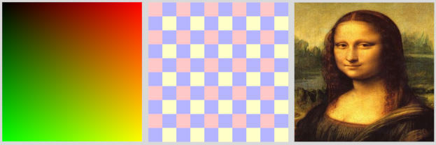
Texture coordinates for the square range from (0,0) at the top left corner of the square to (1,1) at the bottom right corner. For the square on the left in the picture, the texture coordinates for a point on the square are used as the red and green components of the color for that point. (There is no texture image. This is a trivial example of a procedural texture (Subsection 7.3.3).) The square on the right uses an image texture, where the "Mona Lisa" image comes from a file. The middle square also uses an image texture, but in this case the colors for the image come from an array of pixel colors that is part of the program. The image is a tiny four-pixel image, with two rows of pixels and two columns. The original texture coordinates on the square are multiplied by 5 before sampling the texture, so that we see 5 copies of the texture across and down the square. (This is a very simple example of a texture transformation (Subsection 4.3.4).)
Although we will spend much of this section on this basic example, you can also look at webgpu/textured_objects.html, which applies textures to three-dimensional shapes, and webgpu/texture_from_canvas.html, which takes the image for a texture from a canvas on the same page.
Sampling is done in the fragment shader. The texture coordinates that are used for sampling could come from anywhere. But most often, texture coordinates are input to the shader program as a vertex attribute. Then, interpolated texture coordinates are passed to the fragment shader, where they are used to sample the texture.
In the sample program, the square is drawn as a triangle-strip with four vertices. There are two vertex attributes, giving the coordinates and the texture coordinates for each vertex. The two attributes are stored interleaved in a single vertex buffer (see Subsection 9.1.6). The data comes from this array:
const vertexData = new Float32Array([
   /* coords */     /* texcoords */
    -0.8, -0.8,       0, 1,      // data for bottom left corner
     0.8, -0.8,       1, 1,      // data for bottom right corner
    -0.8,  0.8,       0, 0,      // data for top left corner
     0.8,  0.8,       1, 0,      // data for top right corner
]);
Note that the texture coordinates for the top left corner are (0,0) and for the bottom right corner are (1,1). You should check out how this corresponds to the colors on the first square in the illustration. When used to map an image texture onto the square (with no texture transformation), the square will show one full copy of the image, in its usual orientation. If the OpenGL convention for texture coordinates were used on the square, texture coordinates (0,0) would be assigned to the bottom left corner of the square, and the image would appear upside-down. To account for this, images in OpenGL are often flipped vertically before loading the image data into a texture. See the end of Subsection 6.4.2. If you use geometric models that come with texture coordinates, they might well be texture coordinates designed for OpenGL, and you might find that you need to flip your images to get them to apply correctly to the model. This is true, for example, in the textured objects example.
9.5.2 Textures and Samplers
Textures and samplers are created on the JavaScript side of a WebGPU program and are used on the GPU side, where they are used in the fragment shader. This means that they are shader resources. Like other resources, they are declared as global variables in the shader program. Their values are passed to the shader in bind groups, so a sampler or texture variable must be declared with @group and @binding annotations. As an example, the declaration of a variable, tex, that represents a 2D image texture resource could look like this:
@group(0) @binding(0) var tex : texture_2d<f32>;
The type name texture_2d<f32> refers to a 2D texture with samples of type f32; that is, the color returned by sampling the texture will be of type vec4f. A 1D texture with floating point samples would use type name texture_1d<f32>, and there are similar names for 3D and cube textures. (There are also integer textures with type names like texture_2d<u32> and texture_1d<i32>, but they are not used with samplers. They are discussed later in this section.)
Note that a texture variable is declared using var with no address space. (Not like var<uniform> for variables in the uniform address space.) The same is true for sampler variables. Textures and samplers are considered to be in a special "handle" address space, but that name is not used in shader programs.
Sampler variables are declared using type name sampler. (Unfortunately, this means that you can't use "sampler" as the name of a variable.) For example:
@group(0) @binding(1) var samp : sampler;
A sampler is a simple data structure that specifies certain aspects of the sampling process, such as the minification filter and whether to use anisotropic filtering.
Values for texture and sampler variables are constructed on the JavaScript side. A shader program has no direct access to the internal structure of a texture or sampler. In fact, the only thing you can do with them in WGSL is pass them as parameters to functions. There are several built-in functions for working with textures (most of them too obscure to be covered here). The main function for sampling textures is textureSample(). Its parameters are a floating-point texture, a sampler, and texture coordinates. For example,
let textureColor = textureSample ( tex, samp, texcoords );
This function can be used for sampling 1D, 2D, 3D, and cube textures. For a 1D texture, the texcoords parameter is an f32; for a 2D texture, it is a vec2f; and for a 3D or cube texture, it's a vec3f. The return value is a vec4f representing an RGBA color. The return value is always a vec4f, even when the texture does not actually store four color components. For example, a texture might store just one color component; when it is sampled using textureSample(), the color value from the texture will be used as the red component of the color, the green and blue color components will be set to 0.0, and the alpha component will be 1.0.
You should now be able to understand the fragment shader source code from the sample program. Most of the work is on the JavaScript side, so the shader code is quite simple:
@group(0) @binding(0) var samp : sampler;  // Sampler resource from JavaScript.
@group(0) @binding(1) var tex : texture_2d<f32>;  // Image texture resource.

@group(0) @binding(2) var<uniform> textureSelect: u32;
    // Value is 1, 2, or 3 to tell the fragment shader which texture to use.

@fragment
fn fragmentMain(@location(0) texcoords : vec2f) -> @location(0) vec4f {
   if (textureSelect == 1) { // Trivial procedural texture.
           // Use texcoords as red/green color components.
      return vec4f( texcoords, 0, 1);
   }
   else if (textureSelect == 2) { // For the checkerboard texture.
          // Apply texture transform: multiply texcoords by 5.
      return textureSample( tex, samp, 5 * texcoords );
   }
   else { // For the Mona Lisa texture; no texture transform.
      return textureSample( tex, samp, texcoords );
   }
}
Because of the limited options, textures and samplers are fairly simple to use in the shader program. Most of the work is on the JavaScript side.
The purpose of a sampler in WebGPU is to set options for the sampling process. Samplers are created using the JavaScript function device.createSampler(). The following code creates a typical sampler for high-quality sampling of a 2D texture:
let sampler = device.createSampler({
   addressModeU: "repeat",  // Default is "clamp-to-edge".
   addressModeV: "repeat",  //    (The other possible value is "mirror-repeat".)
   minFilter: "linear",
   magFilter: "linear",     // Default for filters is "nearest".
   mipmapFilter: "linear",
   maxAnisotropy: 16        // 1 is the default; 16 is the maximum.
});
The addressModeU property specifies how to treat values of the u texture coordinate that are outside the range 0 to 1, addressModeV does the same for the v coordinates, and for 3D textures there is also addressModeW. (In OpenGL and WebGL, this was called "wrapping"; see Subsection 4.3.3. The meanings are the same here.)
Filtering accounts for the fact that an image usually has to be stretched or shrunk when it is applied to a surface. The magFilter, or magnification filter, is used when stretching an image. The minFilter, or minification filter, is used when shrinking it. Mipmaps are reduced-size copies of the image that can make filtering more efficient. Textures don't automatically come with mipmaps; the mipmapFilter is ignored if no mipmaps are available. This is all similar to OpenGL; see Subsection 4.3.2.
The maxAnisotropy property controls anisotropic filtering, which is explained in Subsection 7.5.1. The default value, 1, says that anisotropic filtering is not used. Higher values give better quality for textures that are viewed edge-on. The maximum value depends on the device, but it's OK to specify a value larger than the maximum; in that case, the maximum value will be used.
Textures are created on the JavaScript side using device.createTexture(). But it is important to understand that this function only allocates the memory on the GPU that will hold the texture data. The actual data will have to be stored later. This is similar to creating a GPU buffer. Here is how the checkerboard texture is created in the sample program:
let checkerboardTexture = device.createTexture({
   size: [2,2],  // Two pixels wide by two pixels high.
   format: "rgba8unorm",  // One 8-bit unsigned int for each color component.
   usage: GPUTextureUsage.TEXTURE_BINDING | GPUTextureUsage.COPY_DST
});
This is a 2D texture, which is the default. The size property specifies the width and height of the texture, either as an array or as an object, {width: 2, height: 2}. The texture format specified here, "rgba8unorm", is a common one for images: four RGBA color components for each pixel, with 8 bits for each color component. The "unorm" in the name means that the 8 bits represent unsigned integers in the range 0 to 255 which are scaled to the range 0.0 to 1.0 to give a floating-point color value. (The scaling is referred to as "normalizing" the values—yet another meaning of the overworked term "normal.") In the usage property, TEXTURE_BINDING, means that the texture can be sampled in a shader program, and COPY_DST means that data can be copied into the texture from elsewhere. It is also possible to fill a texture with data by attaching the texture to a pipeline as a render target; that requires the usage GPUTextureUsage.RENDER_ATTACHMENT. The other possible usage is COPY_SRC, which allows the texture to be used as a source of copied data.
The size, format, and usage properties are required. There are a few optional properties. The mipLevelCount property specifies the number of mipmaps that you will provide for the texture. The default value, 1, means that only the main image will be provided. The dimension property can be "1d", "2d", or "3d", with a default of "2d". The sampleCount property has a default value of 1 and can be set to 4 to create a multisampled texture.
We have already used device.createTexture() to create the special purpose textures that are used for multisampling and for the depth test. See, for example, webgpu/depth_test.html. Those textures were used as render attachments, and the data for the textures were created by drawing an image.
Data for image textures often comes from the JavaScript side of the program. When the data comes from an ArrayBuffer or typed array, the data can be copied to the texture using the function device.queue.writeTexture(). In the sample program, the data for the tiny checkerboard texture comes from a Uint8Array and is copied to the texture with
device.queue.writeTexture(
    { texture: checkerboardTexture }, // Texture to which data will be written.
    textureData,         // A Uint8Array containing the data to be written.
    { bytesPerRow: 8 },  // How many bytes for each row of texels.
    [2,2]   // Size of the texture (width and height).
);
The first parameter to writeTexture() is an object. In addition to the texture property, the object can have a mipLevel property to copy the data into one of the texture's mipmaps, and an origin property to copy the data into a rectangular subregion within the texture. (The origin can be given as an array of integers; together with the size parameter to the function, it determines the rectangular region.) The third parameter is also an object. The bytesPerRow property is the distance, in bytes, from the start of one row of texels to the start of the next row of texels. There can be padding between rows, which is sometimes necessary to satisfy alignment requirements. There can also be an offset property, giving the starting point, in bytes, of the data within the data source.
All of this might seem overly complicated, but textures and images are complex, and the functions that work with them can have many options.
Often, the data source for a texture is an image file. WebGPU cannot take the data directly from an image file; you have to fetch the file and extract the data into an ImageBitmap object. The fetch API, which uses promises, is discussed in Section A.4. Here, for example, is the function from textured_objects.html that is used to load textures from image files:
async function loadTexture(URL) {
       // Standard method using the fetch API to get a texture from a ULR.
    let response = await fetch(URL);
    let blob = await response.blob();  // Get image data as a "blob".
    let imageBitmap = await createImageBitmap(blob);
    let texture = device.createTexture({
        size: [imageBitmap.width, imageBitmap.height],
        format: 'rgba8unorm',
        usage: GPUTextureUsage.TEXTURE_BINDING | GPUTextureUsage.COPY_DST |
                    GPUTextureUsage.RENDER_ATTACHMENT
    });
    device.queue.copyExternalImageToTexture(
       { source: imageBitmap, flipY: true },
       { texture: texture },
       [imageBitmap.width, imageBitmap.height]
    );
    return texture;
}
The texture's usage property is required by copyExternalmageToTexture(). The flipY property is used because the program uses OpenGL-style texture coordinates on the objects that it displays. The source property could also be a canvas, as is done in texture_from_canvas.html. This loadTexture() function must be called from an async function using await, and it is a good idea to catch the errors that might occur:
let texture;
try {
   texture = await loadTexture(URL);
}
catch (e) {
   ...
I will not discuss this in any more detail. See the sample programs for more examples.
Samplers and textures that are created on the JavaScript side must be passed to a shader program as bind group resources. In the bind group, the resource for a sampler is the sampler itself, while the resource for a texture is a view of the texture. Here for example is the bind group for the checkerboard texture in first_texture.html:
checkerboardBindGroup = device.createBindGroup({
   layout: bindGroupLayout,
   entries: [
      {    // The sampler. Note that the resource is the sampler itself.
         binding: 0,
         resource: checkerboardSampler
      },
      {    // The texture.  Note that the resource is a view of the texture.
         binding: 1,
         resource: checkerboardTexture.createView()
      },
      {    // The resource is the buffer containing the uniform variable.
         binding: 2,
         resource: {buffer: uniformBuffer, offset: 0, size: 4}
      }
   ]
});
9.5.3 Mipmaps
Mipmaps are important for quality and efficiency when a texture has to be "minified" to fit a surface. When working with mipmaps, mip level 0 is the original image, mip level 1 is a half-size copy, mip level 2 is a quarter-size copy, and so on. To be exact, if width is the width of the original image, then the width of mip level i is max(1, width >> i), and similarly for the height. For a full set of mipmaps, the process continues until all dimensions have been reduced to 1.
WebGPU has no method for automatically generating mipmaps, but it is not hard to write a WebGPU program to create them on the GPU. The sample program webgpu/making_mipmaps.html shows how to do this. It defines a function that can be used to create a texture with a full set of mipmaps from an ImageBitmap. The program also serves as an example of rendering to a texture and using texture views.
When creating a texture, the number of mipmaps must be specified. It is easy to count the number of mipmaps needed for a full set, given the image bitmap that will be used for level 0:
let mipmapCount = 1;
let size = Math.max(imageBitmap.width,imageBitmap.height);
while (size > 1) {
    mipmapCount++;
    size = size >> 1;
}
let texture = device.createTexture({
    size: [imageBitmap.width, imageBitmap.height],
    mipLevelCount: mipmapCount, // Number of mipmaps.
    format: 'rgba8unorm',
    usage: GPUTextureUsage.TEXTURE_BINDING | GPUTextureUsage.COPY_DST |
                GPUTextureUsage.RENDER_ATTACHMENT
});
The function copyExternalImageToTexture() can be used to copy the bitmap to level 0 in the texture in the usual way. Then each of the remaining mipmap images can be generated in turn by making a half-size copy of the previous level image. The idea is to attach the mipmap as the render target of a pipeline and use the previous mipmap level as a texture resource for the pipeline. Then draw a square that just covers the output, with texture coordinates that map the entire resource image onto the output.
Recall that texture resources and render targets are actually views of textures. We have been using texture.createView(), with no parameter, to create texture views. The result is a view that includes all the mipmaps that the texture has. But it is possible to create a view that contains just a subset of available mipmaps by passing a parameter to createView() that specifies the first mipmap and the number of mipmaps to include in the view. To create a view the contains only mip level i:
textureView = texture.createView({
    baseMipLevel: i,  // First mip level included in this view.
    mipLevelCount: 1  // Only include one mip level.
});
This will let us use a single mipmap from a texture as a texture resource or render target. Here, for example, is the loop from the sample program that creates the mipmap images:
for (let mipmap = 1; mipmap < mipmapCount; mipmap++) {
    let inputView = texture.createView(  // Used as a bind group resource.
                             { baseMipLevel: mipmap - 1, mipLevelCount: 1 });
    let outputView = texture.createView( // Used as a render target.
                             { baseMipLevel: mipmap, mipLevelCount: 1 });
    let renderPassDescriptor = {
       colorAttachments: [{
           loadOp: "load",
           storeOp: "store",
           view: outputView  // Render to mipmap.
       }]
    };
    let bindGroup = webgpuDevice.createBindGroup({
       layout: pipeline.getBindGroupLayout(0),
       entries: [ { binding: 0, resource: sampler },
                  { binding: 1, resource: inputView } ]
    });
    let passEncoder = commandEncoder.beginRenderPass(renderPassDescriptor);
    passEncoder.setPipeline(pipeline);
    passEncoder.setVertexBuffer(0,vertexBuffer); // Coords and texcoords.
    passEncoder.setBindGroup(0,bindGroup); // Includes previous mipmap level.
    passEncoder.draw(4); // Draw square as a triangle-strip.
    passEncoder.end();
}
9.5.4 Cubemap Textures
A cubemap texture consists of six images, one for each side of a cube. The images must be square and must all be the same size. A cubemap texture can be used, for example, to make a skybox (Subsection 5.3.4) and to do environment mapping (also called reflection mapping, Subsection 7.3.5). The sample program webgpu/cubemap_texture.html shows how to create a cubemap texture in WebGPU and how to use it for a skybox and for environment mapping. It is functionally identical to the WebGL example webgl/skybox-and-env-map.html.
In addition to "2d" image textures, WebGPU has "2d-array" textures. A 2d-array texture is just that—an array of 2d images. The elements of the array are called "layers". I do not cover array textures in this textbook, but you need to know a little about them since, for some purposes, a cubemap texture is treated as an array with six layers. The images at indices 0 through 5 are the +X, -X, +Y, -Y, +Z, and -Z sides of the cube, in that order. In particular, a cubemap texture is treated as an array when creating the texture and loading the images for the six sides. Here is some (edited) code from the sample program for loading the texture:
let urls = [  // Links to the six images for the cube.
   "cubemap-textures/park/posx.jpg", "cubemap-textures/park/negx.jpg",
   "cubemap-textures/park/posy.jpg", "cubemap-textures/park/negy.jpg",
   "cubemap-textures/park/posz.jpg", "cubemap-textures/park/negz.jpg"
];
let texture;
for (let i = 0; i < 6; i++) {
    let response = await fetch( urls[i] ); // Get image number i.
    let blob = await response.blob();
    let imageBitmap = await createImageBitmap(blob);
    if (i == 0) { // (We need to know the image size to create the texture.)
        texture = device.createTexture({
            size: [imageBitmap.width, imageBitmap.height, 6],
                // (The 6 at the end means that there are 6 images.)
            dimension: "2d",  // (This is the default texture dimension.)
            format: 'rgba8unorm',
            usage: GPUTextureUsage.TEXTURE_BINDING | GPUTextureUsage.COPY_DST |
                        GPUTextureUsage.RENDER_ATTACHMENT
        });
    }
    device.queue.copyExternalImageToTexture(
       { source: imageBitmap },
       { texture: texture,  origin: [0, 0, i] },
            // The i at the end puts the image into side number i of the cube.
       [imageBitmap.width, imageBitmap.height]
    );
}
For a texture with dimension "2d", the third element in the size property makes the texture into an array texture. (For a "3d" texture, the third element would be the size in the z direction.) Similarly, when copying an image into the texture, the third element of the origin property specifies the array layer into which the image is to be copied.
(When I first wrote the program, using the above code, the environment mapping looked really bad, compared to the WebGL version. This was most apparent on sharply curved surfaces such as the handle of the teapot. Eventually, I realized that the difference was that the WebGL version uses mipmaps. So, I added code to the WebGPU version to produce mipmaps for the cubemap texture. I also added an option to turn the use of mipmaps on and off, so that you can see the difference.)
In a WGSL shader program, cubemap textures are used similarly to 2D textures. The data type for a cubemap texture is texture_cube<f32>. For sampling the texture, the same textureSample() function is used as for 2D textures, but the third parameter, which gives the texture coordinates, is a vec3f. The sample is obtained by casting a ray from the origin in the direction of the vec3f, and seeing where it intersects the cube. For a skybox, which basically shows the view of the box from the inside, the texture coordinates are just the object coordinates of a point on the box. So, the fragment shader for drawing the skybox background is simply
@group(1) @binding(0) var samp: sampler;
@group(1) @binding(1) var cubeTex : texture_cube<f32>;
@fragment fn fmain(@location(0) objCoords : vec3f) -> @location(0) vec4f {
     return textureSample(cubeTex, samp, objCoords);
}
For environment mapping, the idea is to cast a ray from the viewer to a point on the reflective object, and use the reflection of that ray from the surface as the texture coordinate vector: The point where the reflected ray hits the skybox is the point that will be seen by the user on the reflective object. Since the skybox in the sample program can be rotated, the direction of the ray has to be adjusted to take that rotation into account. See Subsection 7.3.5 for a full discussion of the math. Here is the fragment shader for drawing the reflected object:
@group(1) @binding(0) var samp: sampler;
@group(1) @binding(1) var cubeTex : texture_cube<f32>;
@group(1) @binding(2) var<uniform> normalMatrix : mat3x3f;
@group(1) @binding(3) var<uniform> inverseViewTransform : mat3x3f;
@fragment fn fmain(
            @location(0) eyeCoords: vec3f, // Direction from viewer to surface.
            @location(1) normal: vec3f // Untransformed normal to surface.
       ) -> @location(0) vec4f {
     let N = normalize(normalMatrix * normal); // Normal vector to the surface.
     let R = reflect( eyeCoords, N );  // Reflected direction (towards skybox).
     let T = inverseViewTransform * R;
           // Multiplying by inverse of the view transform accounts
           //    for the rotation of the skybox.
     return textureSample(cubeTex, samp, T); // Use reflected ray to sample.
}
On the JavaScript side, again, cubemap textures are used similarly to 2D textures. The samplers that are used for cubemap textures are the same as those used for 2D textures. And a view of the cubemap texture is passed to the shader program as a bind group resource. One difference is that when creating a view, you need to specify that you want to view the texture as a cube texture:
cubeTexture.createView({dimension: "cube"})
By default, it would be viewed as a 2d array texture. When creating mipmaps for the texture, I needed views of the texture to represent a single mipmap level of a single side of the cube. For example,
let outputView = cubeTexture.createView({
                    dimension: "2d",
                    baseMipLevel: mipmap, mipLevelCount: 1,
                    baseArrayLayer: side, arrayLayerCount: 1
                  });
where mipmap is the desired mipmap level and side is the array index for the desired side of the cube. The dimension must be explicitly specified as "2d". (All this might help you understand the difference between a texture and a view of a texture.)
9.5.5 Texture Formats
The format of a texture specifies what kind of data is stored for each texel. The format specifies the number of color channels, the type of data, and in some cases how the data is interpreted. In the common 2D image format "rgba8unorm", there are four color channels ("r", "g", "b", and "a"). The data for a texel consists of 8 bits per color channel. And the value for a color channel is an unsigned integer ("u") in the range 0 to 255, which is divided by 255 to give a float value in the range 0.0 to 1.0 ("norm"). The format "bgra8unorm" is similar, but the order of the "r", "g", and "b" values is reversed. (One of these two formats, depending on platform, is the format for an HTML canvas; the function navigator.gpu.getPreferredCanvasFormat() returns the correct one for your platform. However, using the wrong format will not stop your program from working, since WebGPU does some format conversions automatically when reading and writing textures.)
WebGPU supports a large number of texture formats. There are formats with one color channel ("r"), two color channels ("rg"), and four color channels ("rgba"). The number of bits per color channel can be 8, 16, or 32. The data type can be float, unsigned integer, or signed integer. Some of the integer formats are normalized, but most are not. (There are also compressed texture formats, which are not covered in this textbook.)
For example, the formats "r8uint", "r16uint", and "r32uint" are unsigned integer formats with one color channel and storing one 8-, 16-, or 32-bit unsigned integer per texel. For two 16-bit signed integers per texel, the format would be "rg16sint". The format "rgba32float" uses four 32-bit floating-point numbers per texel.
All textures can be passed into shader programs as resources in bind groups, but only floating-point textures can be sampled using textureSample(). (This includes normalized integer formats.) However, the standard WGSL function textureLoad() can be used to read texel data from a texture, and it works both for integer and for floating-point textures. This function treats the texture like an array: Instead of using texture coordinates to sample the texture, you use integer texel coordinates to access the value at a specified texel. For example, to read from the texel in row 7, column 15 of a texture_2d<u32>, tex, you can use
let texelValue : vec4u = textureLoad( tex, vec2u(7,15), 0 );
The third parameter is the mipmap level, which is required but will usually be zero.
The return value from textureLoad() is always a 4-component vector, even when the texture has only one or two color channels. The missing color channels are filled in with 0 for the "g" or "b" channel, and 1 for the "a" channel. (Note that the term "color" is used for integer textures, even though the values in the texture probably don't represent colors. Floating-point textures can also store data other than colors.)
It is also possible for a shader program to write texel data to a texture, using the function textureStore(). However, the texture has to be passed into the shader as what is called a "storage texture," and this only works for certain texture formats. (There are lots of rules about what can be done with various texture formats. The rules are summarized in a table of Texture Format Capabilities in Section 26.1 of the WebGPU specification.)
In a shader, a storage texture has a type such as texture_storage_2d<r32uint,write>. The first type parameter, r32uint, is the texture format, and the second, write, specifies the access mode. (Currently, write is the only possibility.) The texture is passed into the shader as a bind group resource, with resource type storageTexture, rather than texture. Here, for example, is a bind group layout for a shader program that uses two r32uint textures, one for reading with textureLoad() and one for writing with textureStore():
let bindGroupLayout = device.createBindGroupLayout({
   entries: [
      {    // for a texture_2d<u32> variable in the fragment shader
         binding: 0,
         visibility: GPUShaderStage.FRAGMENT,
         texture: {
            sampleType: "uint"  // Texel values are unsigned integers.
              // (Yes, it's called sampleType even though you can't sample it!)
         }
      },
      {    // for a texture_storage_2d<r32uint,write> in the fragment shader
         binding: 1,
         visibility: GPUShaderStage.FRAGMENT,
         storageTexture: {
            format: "r32uint",
            access: "write-only",  // This is the only possible value.
            viewDimension: "2d"    // This is the default.
         }
      }
   ]
});
Note that "storage texture" just means a texture that has been passed to the shader as a bind group resource of type textureStorage. The same texture could be used as a regular texture or as a storage texture, or both at different times.
The textureStore() function takes three parameters: the texture, the texel coordinates of the texel whose value is to be set, and the value. The value is always a 4-component vector, even if the texture has fewer than four color channels. The missing channels should be specified as 0 for the "g" or "b" channel and as 1 for the "a" channel. For example to set the single integer value at row 7, column 15 in a 2D r32uint storage texture to 17, you could use
textureStore( tex, vec2u(7,15), vec4u(17,0,0,1) );
The sample program webgpu/life_1.html implements John Conway's well-known Game of Life (see Subsection 6.4.5). The game board is a 2D array of cells, where each cell can be alive or dead. In the program, the state of the board is stored as a 2D texture of type r32uint, with 0 representing a dead cell and 1 representing a living cell. The game board is displayed on a canvas, and each pixel in the canvas is a cell. So, the size of the texture is the same as the size of the canvas.
The action of the game involves computing a new "generation" of cells from the current generation. The program actually uses two textures: a regular texture containing the current generation of the board and a storage texture that is used to store the next generation as it is computed. The program does all its work in its draw() function. That function draws a square that completely covers the canvas, so that the fragment shader is called once for each pixel on the canvas. The fragment shader uses textureLoad() to read the current state of the cell that it is processing. If the cell is alive, it returns white as the color of the fragment; if the cell is dead, it returns black. At the same time, the fragment shader computes the state of the cell in the next generation, and it writes that state to the storage texture using textureStore(). Between draws, the roles of the two textures are swapped, so that what was the next generation becomes the current generation.
Here is the fragment shader, leaving out the part that computes the new state of the cell. It uses another new function, textureDimensions(), which gets the size of a texture in each of its dimensions. That value is required for the new state computation.
@group(0) @binding(0) var inputBoard: texture_2d<u32>;
@group(0) @binding(1) var outputBoard: texture_storage_2d<r32uint,write>;

@fragment
fn fragmentMain(@builtin(position) position : vec4f) -> @location(0) vec4f {
   let boardSize = textureDimensions(inputBoard);
   let cell = vec2u(position.xy); // Integer pixel coords of this fragment.
   let alive = textureLoad( inputBoard, cell, 0 ).r;  // Get current state.
                  // (Note that the state is in the r color component.)
      .
      . // (Compute newAlive, the state of the cell in the next generation,)
      .
   textureStore( outputBoard, cell, vec4u(newAlive,0,0,1) ); // Store new state.
   let c = f32(alive);
   return vec4f(c,c,c,1); // White if cell is now alive, black if it is dead.
}
The program creates two textures, texture1 and texture2, and loads texture1 with the initial state of the board. Here is the bind group that assigns texture1 to inputBoard in the shader and texture2 to outputBoard. It uses the sample bind group layout shown above.
bindGroupA = device.createBindGroup({
      // A bind group using texture1 for input and texture2 for output.
   layout: bindGroupLayout,
   entries: [
      {
         binding: 0,
         resource: texture1.createView()
      },
      {
         binding: 1,
         resource: texture2.createView()
      }
   ]
});
A second bind group, bindGroupB, reverses the roles of the textures. The program uses bindGroupA the first time draw() is called, bindGroupB the second time, bindGroupA the third time, and so on.
A second version of the Life program, webgpu/life_2.html, uses a different approach. It uses two textures with format "r8unorm" to represent the current state and the next state of the board. A texture with that format can be used for sampling in a shader program, so values can be read from the input board using textureSample() instead of textureLoad(). And a r8unorm texture can be an output target for a render pipeline. The fragment shader can then have two outputs, one going to the canvas and one going to the r8unorm texture.
To have a second output from the fragment shader, the pipeline descriptor must specify two targets:
let pipelineDescriptor = {
        ...
    fragment: {
       module: shader,
       entryPoint: "fragmentMain",
       targets: [
            { format: navigator.gpu.getPreferredCanvasFormat() },
            { format: "r8unorm"}
       ]
    },
       ...
Then the render pass descriptor uses a view of the output texture as the second color attachment:
let renderPassDescriptor = {
   colorAttachments: [
      {
         clearValue: { r: 0, g: 0, b: 0, a: 1 },
         loadOp: "clear",
         storeOp: "store",
         view: context.getCurrentTexture().createView()
      },
      {  // The second color attachment is a r8unorm texture.
         loadOp: "load", // (OK here since contents are entirely replaced.)
         storeOp: "store",
         view: outputTexture.createView()
      }
   ]
};
The output type for the fragment shader is a struct that contains the two output values. For full details, you should, of course, look at the source code for the two sample Life programs.
Textures are complex. I have only covered parts of the API. But I have tried to give you an overview that includes most of the information that you are likely to need.