Section 13.2
Fancier Graphics
The graphics commands provided by the Graphics class are sufficient for many purposes. However, recent versions of Java provide a much larger and richer graphical toolbox in the form of the class java.awt.Graphics2D. I mentioned Graphics2D in Subsection 6.3.5 and promised to discuss it further in this chapter.
Graphics2D is a subclass of Graphics, so all of the graphics commands that you already know can be used with a Graphics2D object. In fact, when you obtain a Graphics context for drawing on a Swing component or on a BufferedImage, the graphics object is actually of type Graphics2D and can be type-cast to gain access to the advanced Graphics2D graphics commands. Furthermore, BufferedImage has an instance method, createGraphics(), that returns a graphics context of type Graphics2D. For example, if image is of type BufferedImage, then you can get a Graphics2D for drawing on the image using:
Graphics2D g2 = image.createGraphics();
And, as mentioned in Subsection 6.3.5, to use Graphics2D commands in the paintComponent() method of a Swing component, you can write a paintComponent() method of the form:
public void paintComponent(Graphics g) {
   super.paintComponent(g);
   Graphics g2 = (Graphics2D)g;
      .
      .   // Draw to the component using g2 (and g).
      .
}
Note that when you do this, g and g2 are just two variables that refer to the same object, so they both draw to the same drawing surface; g2 just gives you access to methods that are defined in Graphics2D but not in Graphics. When properties of g2, such as drawing color, are changed, the changes also apply to g. By saying
Graphics2D g2 = (Graphics2D)g.create()
you can obtain a newly created graphics context. The object created by g.create() is a graphics context that draws to the same drawing surface as g and that initially has all the same properties as g. However, it is a separate object, so that changing properties in g2 has no effect on g. This can be useful if you want to keep an unmodified copy of the original graphics context around for some drawing operations. (In this case, it is good practice to call g2.dispose() to dispose of the new graphics context when you are finished using it.)
13.2.1 Measuring Text
Although this section is mostly about Graphics2D, we start with a topic that has nothing to do with it.
Often, when drawing a string, it's important to know how big the image of the string will be. For example, you need this information if you want to center a string in a component. Or if you want to know how much space to leave between two lines of text, when you draw them one above the other. Or if the user is typing the string and you want to position a cursor at the end of the string. In Java, questions about the size of a string can be answered by an object belonging to the standard class java.awt.FontMetrics.
There are several lengths associated with any given font. Some of them are shown in this illustration:
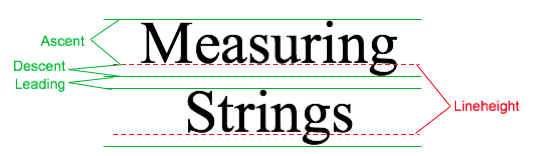
The dashed red lines in the illustration are the baselines of the two lines of text. The baseline of a string is the line on which the bases of the characters rest. The suggested distance between two baselines, for single-spaced text, is known as the lineheight of the font. The ascent is the distance that tall characters can rise above the baseline, and the descent is the distance that tails like the one on the letter "g" can descend below the baseline. The ascent and descent do not add up to the lineheight, because there should be some extra space between the tops of characters in one line and the tails of characters on the line above. The extra space is called leading. (The term comes from the time when lead blocks were used for printing. Characters were formed on blocks of lead that were lined up to make up the text of a page, covered with ink, and pressed onto paper to print the page. Extra, blank "leading" was used to separate the lines of characters.) All these quantities can be determined by calling instance methods in a FontMetrics object. There are also methods for determining the width of a character and the total width of a string of characters.
Recall that a font in Java is represented by the class Font. A FontMetrics object is associated with a given font and is used to measure characters and strings in that font. If font is of type Font and g is a graphics context, you can get a FontMetrics object for the font by calling g.getFontMetrics(font). If fm is the variable that refers to the FontMetrics object, then the ascent, descent, leading, and lineheight of the font can be obtained by calling fm.getAscent(), fm.getDescent(), fm.getLeading(), and fm.getHeight(). If ch is a character, then fm.charWidth(ch) is the width of the character when it is drawn in that font. If str is a string, then fm.stringWidth(str) is the width of the string when drawn in that font. For example, here is a paintComponent() method that shows the message "Hello World" in the exact center of the component:
public void paintComponent(Graphics g) {
   super.paintComponent(g);

   int strWidth, strHeight; // Width and height of the string.
   int centerX, centerY;    // Coordinates of the center of the component.
   int baseX, baseY;        // Coordinates of the basepoint of the string.
   int topOfString;         // y-coordinate of the top of the string.

   centerX = getWidth() / 2;
   centerY = getHeight() / 2;

   Font font = g.getFont();  // What font will g draw in?
   FontMetrics fm = g.getFontMetrics(font);
   strWidth = fm.stringWidth("Hello World");
   strHeight = fm.getAscent();  // Note: There are no tails on
                                //   any of the chars in the string!

   baseX = centerX - (strWidth/2);  // Move back from center by half the
                                    //    width of the string.

   topOfString = centerY - (strHeight/2);  // Move up from center by half
                                           //   the height of the string.

   baseY = topOfString + fm.getAscent();  // Baseline is fm.getAscent() pixels
                                          //   below the top of the string.

   g.drawString("Hello World", baseX, baseY); // Draw the string.
}
You can change the font that is used for drawing strings as described in Subsection 6.3.3. For the height of the string in this method, I use fm.getAscent(). If I were drawing "Goodbye World" instead of "Hello World," I would have used fm.getAscent() + fm.getDescent(), where the descent is added to the height in order to take into account the tail on the "y" in "Goodbye". The value of baseX is computed to be the amount of space between the left edge of the component and the start of the string. It is obtained by subtracting half the width of the string from the horizontal center of the component. This will center the string horizontally in the component. The next line computes the position of the top of the string in the same way. However, to draw the string, we need the y-coordinate of the baseline, not the y-coordinate of the top of the string. The baseline of the string is below the top of the string by an amount equal to the ascent of the font.
There is an example of centering a two-line block of text in the sample program TransparencyDemo.java, which is discussed in the next subsection.
13.2.2 Transparency
A color is represented by red, blue, and green components. In Java's usual representation, each component is an eight-bit number in the range 0 to 255. The three color components can be packed into a 32-bit integer, but that only accounts for 24 bits in the integer. What about the other eight bits? They don't have to be wasted. They can be used as a fourth component of the color, the alpha component. The alpha component can be used in several ways, but it is most commonly associated with transparency. When you draw with a transparent color, it's like laying down a sheet of colored glass. It doesn't completely obscure the part of the image that is colored over. Instead, the background image is blended with the transparent color that is used for drawing -- as if you were looking at the background through colored glass. This type of drawing is properly referred to as alpha blending, and it is not equivalent to true transparency; nevertheless, most people refer to it as transparency.
The value of the alpha component determines how transparent that color is. Actually, the alpha component gives the opaqueness of the color. Opaqueness is the opposite of transparency. If something is fully opaque, you can't see through it at all; if something is almost fully opaque, then it is just a little transparent; and so on. When the alpha component of a color has the maximum possible value, the color is fully opaque. When you draw with a fully opaque color, that color simply replaces the color of the background over which you draw. This is the only type of color that we have used up until now. If the alpha component of a color is zero, then the color is perfectly transparent, and drawing with that color has no effect at all. Intermediate values of the alpha component give partially opaque colors that will blend with the background when they are used for drawing.
Here is an applet that can help you to understand transparency. It shows a triangle, an oval, a rectangle, and some text. Sliders at the bottom of the applet allow you to control the degree of transparency of each shape. When a slider is moved all the way to the right, the corresponding shape is fully opaque; all the way to the left, and the shape is fully transparent. The source code for this program is TransparencyDemo.java.
Colors with alpha components were introduced in Java along with Graphics2D, but they can be used with ordinary Graphics objects as well. To specify the alpha component of a color, you can create the Color object using one of the following constructors from the Color class:
public Color(int red, int green, int blue, int alpha);

public Color(float red, float green, float blue, float alpha);
In the first constructor, all the parameters must be integers in the range 0 to 255. In the second, the parameters must be in the range 0.0 to 1.0. For example,
Color transparentRed = new Color( 255, 0, 0, 200 );
makes a slightly transparent red, while
Color tranparentCyan = new Color( 0.0F, 1.0F, 1.0F, 0.5F);
makes a blue-green color that is 50% opaque. (The advantage of the constructor that takes parameters of type float is that it lets you think in terms of percentages.) When you create an ordinary RGB color, as in new Color(255,0,0), you just get a fully opaque color.
Once you have a transparent color, you can use it in the same way as any other color. That is, if you want to use a Color c to draw in a graphics context g, you just say g.setColor(c), and subsequent drawing operations will use that color. As you can see, transparent colors are very easy to use.
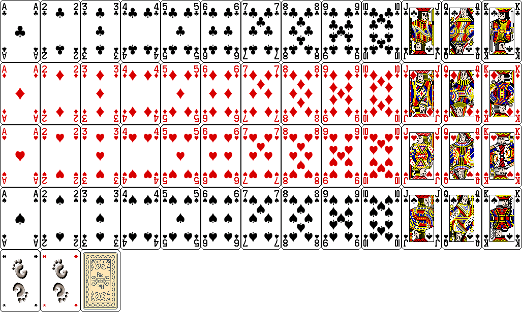
A BufferedImage with image type BufferedImage.TYPE_INT_ARGB can use transparency. The color of each pixel in the image can have its own alpha component, which tells how transparent that pixel will be when the image is drawn over some background. A pixel whose alpha component is zero is perfectly transparent, and has no effect at all when the image is drawn; in effect, it's not part of the image at all. It is also possible for pixels to be partly transparent. When an image is saved to a file, information about transparency might be lost, depending on the file format. The PNG image format supports transparency; JPEG does not. (If you look at the images of playing cards that are used in the program HighLowWithImages in Subsection 13.1.1, you might notice that the tips of the corners of the cards are fully transparent. The card images are from a PNG file, cards.png.)
An ARGB BufferedImage should be fully transparent when it is first created, but if you want to make sure, here is one way of doing so: The Graphics2D class has a method setBackground() that can be used to set a background color for the graphics context, and it has a clearRect() method that fills a rectangle with the current background color. To create a fully transparent image with width w and height h, you can use:
BufferedImage image = new BufferedImage(w, h, BufferedImage.TYPE_INT_ARGB);
Graphics2D g2 = (Graphics2D)image.getGraphics();
g2.setBackground(new Color(0,0,0,0));  // (The R, G, and B values don't matter.)
g2.clearRect(0, 0, w, h);
(Note that simply drawing with a transparent color will not make pixels in the image transparent. The alpha component of a Color makes the color transparent when it is used for drawing; it does not change the transparency of the pixels that are modified by the drawing operation.)
As an example, just for fun, here is a method that will set the cursor of a component to be a red square with a transparent interior:
private void useRedSquareCursor() {
   BufferedImage image = new BufferedImage(24,24,BufferedImage.TYPE_INT_ARGB);
   Graphics2D g2 = (Graphics2D)image.getGraphics();
   g2.setBackground(new Color(0,0,0,0));
   g2.clearRect(0, 0, 24, 24);  // (should not be necessary in a new image)
   g2.setColor(Color.RED);
   g2.drawRect(0,0,23,23);
   g2.drawRect(1,1,21,21);
   g2.dispose();
   Point hotSpot = new Point(12,12);
   Toolkit tk = Toolkit.getDefaultToolkit();
   Cursor cursor = tk.createCustomCursor(image,hotSpot,"square");
   setCursor(cursor);
}
13.2.3 Antialiasing
To draw a geometric figure such as a line or circle, you just have to color the pixels that are part of the figure, right? Actually, there is a problem with this. Pixels are little squares. Geometric figures, on the other hand, are made of geometric points that have no size at all. Think about drawing a circle, and think about a pixel on the boundary of that circle. The infinitely thin geometric boundary of the circle cuts through the pixel. Part of the pixel lies inside the circle, part lies outside. So, when we are filling the circle with color, do we color that pixel or not? A possible solution is to color the pixel if the geometric circle covers 50% or more of the pixel. Following this procedure, however, leads to a visual defect known as aliasing. It is visible in images as a jaggedness or "staircasing" effect along the borders of curved shapes. Lines that are not horizontal or vertical also have a jagged, aliased appearance. (The term "aliasing" seems to refer to the fact that many different geometric points map to the same pixel. If you think of the real-number coordinates of a geometric point as a "name" for the pixel that contains that point, then each pixel has many different names or "aliases.")
It's not possible to build a circle out of squares, but there is a technique that can eliminate some of the jaggedness of aliased images. The technique is called antialiasing. Antialiasing is based on transparency. The idea is simple: If 50% of a pixel is covered by the geometric figure that you are trying to draw, then color that pixel with a color that is 50% transparent. If 25% of the pixel is covered, use a color that is 75% transparent (25% opaque). If the entire pixel is covered by the figure, of course, use a color that is 100% opaque -- antialiasing only affects pixels that are only partly covered by the geometric shape.
In antialiasing, the color that you are drawing with is blended with the original color of the pixel, and the amount of blending depends on the fraction of the pixel that is covered by the geometric shape. (The fraction is difficult to compute exactly, so in practice, various methods are used to approximate it.) Of course, you still don't get a picture of the exact geometric shape, but antialiased images do tend to look better than jagged, aliased images.
For an example, look at the applet in the next subsection. Antialiasing is used to draw the panels in the second and third row of the applet, but it is not used in the top row. You should note the jagged appearance of the lines and rectangles in the top row. (By the way, when antialiasing is applied to a line, the line is treated as a geometric rectangle whose width is equal to the size of one pixel.)
Antialiasing is supported in Graphics2D. By default, antialiasing is turned off. If g2 is a graphics context of type Graphics2D, you can turn on antialiasing in g2 by saying:
g2.setRenderingHint(RenderingHints.KEY_ANTIALIASING,
                                  RenderingHints.VALUE_ANTIALIAS_ON);
As you can see, this is only a "hint" that you would like to use antialiasing, and it is even possible that the hint will be ignored. However, it is likely that subsequent drawing operations in g2 will be antialiased. If you want to turn antialiasing off in g2, you should say:
g2.setRenderingHint(RenderingHints.KEY_ANTIALIASING,
                                  RenderingHints.VALUE_ANTIALIAS_OFF);
13.2.4 Strokes and Paints
When using the Graphics class, any line that you draw will be a solid line that is one pixel thick. The Graphics2D class makes it possible to draw a much greater variety of lines. You can draw lines of any thickness, and you can draw lines that are dotted or dashed instead of solid.
An object of type Stroke contains information about how lines should be drawn, including how thick the line should be and what pattern of dashes and dots, if any, should be used. Every Graphics2D has an associated Stroke object. The default Stroke draws a solid line of thickness one. To get lines with different properties, you just have to install a different stroke into the graphics context.
Stroke is an interface, not a class. The class BasicStroke, which implements the Stroke interface, is the one that is actually used to create stroke objects. For example, to create a stroke that draws solid lines with thickness equal to 3, use:
BasicStroke line3 = new BasicStroke(3);
If g2 is of type Graphics2D, the stroke can be installed in g2 by calling its setStroke() command:
g2.setStroke(line3)
After calling this method, subsequent drawing operations will use lines that are three times as wide as the usual thickness. The thickness of a line can be given by a value of type float, not just by an int. For example, to use lines of thickness 2.5 in the graphics context g2, you can say:
g2.setStroke( new BasicStroke(2.5F) );
(Fractional widths make more sense if antialiasing is turned on.)
When you have a thick line, the question comes up, what to do at the ends of the line. If you draw a physical line with a large, round piece of chalk, the ends of the line will be rounded. When you draw a line on the computer screen, should the ends be rounded, or should the line simply be cut off flat? With the BasicStroke class, the choice is up to you. Maybe it's time to look at examples. This applet shows fifteen lines, drawn using different BasicStrokes. Lines in the middle row have rounded ends; lines in the other two rows are simply cut off at their endpoints. Lines of various thicknesses are shown, and the bottom row shows dashed lines. (And, as mentioned above, only the bottom two rows are antialiased.)
This applet is an applet version of the sample program StrokeDemo.java. In this program, you can click and drag in any of the small panels, and the lines in all the panels will be redrawn as you move the mouse. In addition, if you right-click and drag, then rectangles will be drawn instead of lines; this shows that strokes are used for drawing the outlines of shapes and not just for straight lines. If you look at the corners of the rectangles that are drawn by the program, you'll see that there are several ways of drawing a corner where two wide line segments meet.
All the options that you want for a BasicStroke have to be specified in the constructor. Once the stroke object is created, there is no way to change the options. There is one constructor that lets you specify all possible options:
public BasicStroke( float width, int capType, int joinType, float miterlimit,
                                         float[] dashPattern, float dashPhase )
I don't want to cover all the options in detail, but here's some basic info:
- width specifies the thickness of the line
- capType specifies how the ends of a line are "capped." The possible values are BasicStroke.CAP_SQUARE, BasicStroke.CAP_ROUND and BasicStroke.CAP_BUTT. These values are used, respectively, in the first, second, and third rows of the above applet. The default is BasicStroke.CAP_SQUARE.
- joinType specifies how two line segments are joined together at corners. Possible values are BasicStroke.JOIN_MITER, BasicStroke.JOIN_ROUND, and BasicStroke.JOIN_BEVEL. Again, these are used in the three rows of panels in the above applet; the effect is only seen in the applet when drawing rectangles. The default is BasicStroke.JOIN_MITER.
- miterLimit is used only if the value of joinType is JOIN_MITER; just use the default value, 10.0F.
- dashPattern is used to specify dotted and dashed lines. The values in the array specify lengths in the dot/dash pattern. The numbers in the array represent the length of a solid piece, followed by the length of a transparent piece, followed by the length of a solid piece, and so on. At the end of the array, the pattern wraps back to the beginning of the array. If you want a solid line, use a different constructor that has fewer parameters.
- dashPhase tells the computer where to start in the dashPattern array, for the first segment of the line. Use 0 for this parameter in most cases.
For the third row in the above applet, the dashPattern is set to new float[] {5,5}. This means that the lines are drawn starting with a solid segment of length 5, followed by a transparent section of length 5, and then repeating the same pattern. A simple dotted line would have thickness 1 and dashPattern new float[] {1,1}. A pattern of short and long dashes could be made by using new float[] {10,4,4,4}. For more information, see the Java documentation, or try experimenting with the source code for the sample program.
So now we can draw fancier lines. But any drawing operation is still restricted to drawing with a single color. We can get around that restriction by using Paint. An object of type Paint is used to assign color to each pixel that is "hit" by a drawing operation. Paint is an interface, and the Color class implements the Paint interface. When a color is used for painting, it applies the same color to every pixel that is hit. However, there are other types of paint where the color that is applied to a pixel depends on the coordinates of that pixel. Standard Java includes two classes that define paint with this property: GradientPaint and TexturePaint. In a gradient, the color that is applied to pixels changes gradually from one color to a second color as you move from point to point. In a texture, the pixel colors come from an image, which is repeated, if necessary, like a wallpaper pattern to cover the entire xy-plane.
It will be helpful to look at some examples. Here is an applet that uses Paint objects to fill a polygon. This is an applet version of the sample program PaintDemo.java. You can select among two GradientPaints and two TexturePaints using four buttons at the bottom of the applet. The sliders control properties of the paint. You can drag the vertices of the polygon, to see what it looks when its shape changes. Note that in this applet, the paint is used only for filling the polygon. The outline of the polygon is drawn in a plain black color. However, Paint objects can be used for drawing lines as well as for filling shapes. Try it!
Basic gradient paints are created using the constructor
public GradientPaint(float x1, float y1, Color c1,
                             float x2, float y2, Color c2, boolean cyclic)
This constructs a gradient that has color c1 at the point with coordinates (x1,y1) and color c2 at the point (x2,y2). As you move along the line between the two points, the color of the gradient changes from c1 to c2; along lines perpendicular to this line, the color is constant. The last parameter, cyclic, tells what happens if you move past the point (x2,y2) on the line from (x1,y1) to (x2,y2). If cyclic is false, the color stops changing and any point beyond (x2,y2) has color c2. If cyclic is true, then the colors continue to change in a cyclic pattern after you move past (x2,y2). (It works the same way if you move past the other endpoint, (x1,y1).) In most cases, you will set cyclic to true. Note that you can vary the points (x1,y1) and (x2,y2) to change the width and direction of the gradient. For example, to create a cyclic gradient that varies from black to light gray along the line from (0,0) to (100,100), use:
new GradientPaint( 0, 0, Color.BLACK, 100, 100, Color.LIGHT_GRAY, true)
Java 6 introduced two new gradient paint classes, LinearGradientPaint and RadialGradientPaint. Linear gradient paints are similar to GradientPaint but can be based on more than two colors. Radial gradients color pixels based on their distance from a central point, which produces rings of constant color instead of lines of constant color. See the API documentation for details.
To construct a TexturePaint, you need a BufferedImage that contains the image that will be used for the texture. You also specify a rectangle in which the image will be drawn. The image will be scaled, if necessary, to exactly fill the rectangle. Outside the specified rectangle, the image will be repeated horizontally and vertically to fill the plane. You can vary the size and position of the rectangle to change the scale of the texture and its positioning on the plane. Ordinarily, however the upper left corner of the rectangle is placed at (0,0), and the size of the rectangle is the same as the actual size of the image. The constructor for TexturePaint is defined as
public TexturePaint( BufferedImage textureImage, Rectangle2D anchorRect)
The Rectangle2D is part of the Graphics2D framework and will be discussed at the end of this section. Often, a call to the constructor takes the form:
new TexturePaint( image,
            new Rectangle2D.Double(0,0,image.getWidth(),image.getHeight() )
Once you have a Paint object, you can use the setPaint() method of a Graphics2D object to install the paint in a graphics context. For example, if g2 is of type Graphics2D, then the command
g2.setPaint( new GradientPaint(0,0,Color.BLUE,100,100,Color.GREEN,true) );
sets up g2 to use a gradient paint. Subsequent drawing operations with g2 will draw using a blue/green gradient.
13.2.5 Transforms
In the standard drawing coordinates on a component, the upper left corner of the component has coordinates (0,0). Coordinates are integers, and the coordinates (x,y) refer to the point that is x pixels over from the left edge of the component and y pixels down from the top. With Graphics2D, however, you are not restricted to using these coordinates. In fact, you can can set up a Graphics2D graphics context to use any system of coordinates that you like. You can use this capability to select the coordinate system that is most appropriate for the things that you want to draw. For example, if you are drawing architectural blueprints, you might use coordinates in which one unit represents an actual distance of one foot.
Changes to a coordinate system are referred to as transforms. There are three basic types of transform. A translate transform changes the position of the origin, (0,0). A scale transform changes the scale, that is, the unit of distance. And a rotation transform applies a rotation about some point. You can make more complex transforms by combining transforms of the three basic types. For example, you can apply a rotation, followed by a scale, followed by a translation, followed by another rotation. When you apply several transforms in a row, their effects are cumulative. It takes a fair amount of study to fully understand complex transforms. I will limit myself here to discussing a few of the most simple cases, just to give you an idea of what transforms can do.
Suppose that g2 is of type Graphics2D. Then g2.translate(x,y) moves the origin, (0,0), to the point (x,y). This means that if you use coordinates (0,0) after saying g2.translate(x,y), then you are referring to the point that used to be (x,y), before the translation was applied. All other coordinate pairs are moved by the same amount. For example saying
g.translate(x,y);
g.drawLine( 0, 0, 100, 200 );
draws the same line as
g.drawLine( x, y, 100+x, 200+y );
In the second case, you are just doing the same translation "by hand." A translation (like all transforms) affects all subsequent drawing operations. Instead of thinking in terms of coordinate systems, you might find it clearer to think of what happens to the objects that are drawn. After you say g2.translate(x,y), any objects that you draw are displaced x units horizontally and y units vertically. Note that the parameters x and y can be real numbers.
As an example, perhaps you would prefer to have (0,0) at the center of a component, instead of at its upper left corner. To do this, just use the following command in the paintComponent() method of the component:
g2.translate( getWidth()/2, getHeight()/2 );
To apply a scale transform to a Graphics2D g2, use g2.scale(s,s), where s is the real number that specifies the scaling factor. If s is greater than 1, everything is magnified by a factor of s, while if s is between 0 and 1, everything is shrunk by a factor of s. The center of scaling is (0,0). That is, the point (0,0) is unaffected by the scaling, and other points more towards or away from (0,0) by a factor of s. Again, it can be clearer to think of the effect on objects that are drawn after a scale transform is applied. Those objects will be magnified or shrunk by a factor of s. Note that scaling affects everything, including thickness of lines and size of fonts. It is possible to use different scale factors in the horizontal and vertical direction with a command of the form g2.scale(sx,sy), although that will distort the shapes of objects. By the way, it is even possible to use scale factors that are less than 0, which results in reflections. For example, after calling g2.scale(-1,1), objects will be reflected horizontally through the line x=0.
The third type of basic transform is rotation. The command g2.rotate(r) rotates all subsequently drawn objects through an angle of r about the point (0,0). You can rotate instead about the point (x,y) with the command g2.rotate(r,x,y). All the parameters can be real numbers. Angles are measured in radians, where π radians are equal to 180 degrees. To rotate through an angle of d degrees, use
g2.rotate( d * Math.PI / 180 );
Positive angles are clockwise rotations, while negative angles are counterclockwise (unless you have applied a negative scale factor, which reverses the orientation).
Rotation is not as common as translation or scaling, but there are a few things that you can do with it that can't be done any other way. For example, you can use it to draw an image "on the slant." Rotation also makes it possible to draw text that is rotated so that its baseline is slanted or even vertical. To draw the string "Hello World" with its basepoint at (x,y) and rising at an angle of 30 degrees, use:
g2.rotate( -30 * Math.PI / 180, x, y );
g2.drawString( "Hello World", x, y );
To draw the message vertically, with the center of its baseline at the point (x,y), we can use FontMetrics to measure the string, and say:
FontMetrics fm = g2.getFontMetrics( g2.getFont() );
int baselineLength = fm.stringWidth("Hello World");
g2.rotate( -90 * Math.PI / 180, x, y);
g2.drawString( "Hello World", x - baselineLength/2, y );
The drawing operations in the Graphics class use integer coordinates only. Graphics2D makes it possible to use real numbers as coordinates. This becomes particularly important once you start using transforms, since after you apply a scale, a square of size one might cover many pixels instead of just a single pixel. Unfortunately, the designers of Java couldn't decide whether to use numbers of type float or double as coordinates, and their indecision makes things a little more complicated than they need to be. (My guess is that they really wanted to use float, since values of type float have enough accuracy for graphics and are probably used in the underlying graphical computations of the computer. However, in Java programming, it's easier to use double than float, so they wanted to make it possible to use double values too.)
To use real number coordinates, you have to use classes defined in the package java.awt.geom. Among the classes in this package are classes that represent geometric shapes such as lines and rectangles. For example, the class Line2D represents a line whose endpoints are given as real number coordinates. The unfortunate thing is that Line2D is an abstract class, which means that you can't create objects of type Line2D directly. However, Line2D has two concrete subclasses that can be used to create objects. One subclass uses coordinates of type float, and one uses coordinates of type double. The most peculiar part is that these subclasses are defined as static nested classes inside Line2D. Their names are Line2D.Float and Line2D.Double. This means that Line2D objects can be created, for example, with:
Line2D line1 = new Line2D.Float( 0.17F, 1.3F, -2.7F, 5.21F );
Line2D line2 = new Line2D.Double( 0, 0, 1, 0);
Line2D line3 = new Line2D.Double( x1, y1, x2, y2 );
where x1, y1, x2, y2 are any numeric variables. In my own code, I generally use Line2D.Double rather than Line2D.Float.
Other shape classes in java.awt.geom are similar. The class that represents rectangles is Rectangle2D. To create a rectangle object, you have to use either Rectangle2D.Float or Rectangle2D.Double. For example,
Rectangle2D rect = new Rectangle2D.Double( -0.5, -0.5, 1.0, 1.0 );
creates a rectangle with a corner at (-0.5,-0.5) and with width and height both equal to 1. Other classes include Point2D, which represents a single point; Ellipse2D, which represents an oval; and Arc2D, which represents an arc of a circle.
If g2 is of type Graphics2D and shape is an object belonging to one of the 2D shape classes, then the command
g2.draw(shape);
draws the shape. For a shape such as a rectangle or ellipse that has an interior, only the outline is drawn. To fill in the interior of such a shape, use
g2.fill(shape)
For example, to draw a line from (x1,y1) to (x2,y2), use
g2.draw( new Line2D.Double(x1,y1,x2,y2) );
and to draw a filled rectangle with a corner at (3.5,7), with width 5 and height 3, use
g2.fill( new Rectangle2D.Double(3.5, 7, 5, 3) );
The package java.awt.geom also has a very nice class GeneralPath that can be used to draw polygons and curves defined by any number of points. See the Java documentation if you want to find out how to use it. In Java 6, GeneralPath has been largely superseded by Path2D which provides the same functionality but more closely follows the conventions used by other shape classes.
This section has introduced you to many of the interesting features of Graphics2D, but there is still a large part of the Graphics2D framework for you to explore.