CS 424: Computer Graphics, Fall 2017
Blender Lab 1: Blender Basics
This is the first of four labs that are planned using the 3D modeling and animation program, Blender. The first three Blender labs will take place on consecutive Mondays (October 16, 23, and 30), and they will be graded together after the third lab. The fourth lab will be near the end of the semester.
Blender is a complex program with an interface that takes some getting used to. You should spend this first lab getting acquainted with the basics: 3D objects, transformations, materials, and textures.
It is essential that you read Section B.1 in Appendix B of the textbook before coming to lab. It covers aspects of the Blender interface that I will not repeat here!
Remember to save your work frequently while you are working on your scene. Note that Blender will automatically keep a backup file, with file extension .blend1, when you save a new version. You can render an image with the F12 key, and dismiss the rendered image with the F11 or ESC key. While a rendered image is on-screen, you can save it using the F3 key. There are also menu commands for these functions.
Grading for Blender work will follow the same guidelines as for Gimp and Inkscape. (The grading will be along the lines of: "Not done" for an F; "Minimal effort and incomplete" for a D; "Minimal effort" for a C; "Acceptable" for a B; or "Excellent" for an A. "Excellent" means that your work shows substantial and thoughtful effort, a willingness to investigate and experiment, and some attention to aesthetics.)
Your Blender work for the first three labs should be submitted in a folder named blender inside your homework folder. For this lab, you should submit a copy of your completed Blender file, stage.blend. You should also submit a rendered image of your scene. (Please remember to turn in both!) I will grade all Blender work at the same time, no earlier than Friday, November 10.
Populate the Stage!
You should start with a copy of stage.blend, which you can get from /classes/cs424. If you double-click your copy, it should open with Blender. (If not, start Blender and open the file using the "Open" command in the "File" menu.) The scene in the file is an empty "stage," made from two scaled cubes. Initially, you see the stage in the camera view (Numpad-0). You can see other views with the Numpad 1, 3, and 7 keys; you can rotate the view with the middle mouse button, and you can drag the view by pressing the shift key while dragging with the middle mouse button. See Section B.1 for more information!
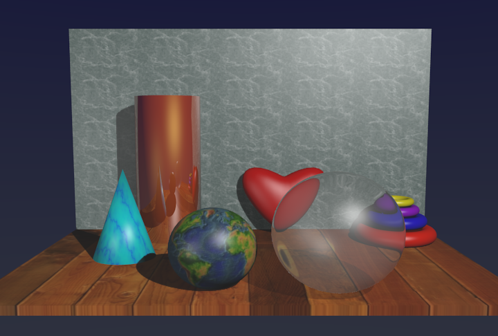
Your job is to place objects on the stage. Use Mesh objects, with at most one or two exceptions. You should assign materials to all the objects, and you should assign textures to some of them. You should use both image textures and procedural textures. You should also assign textures to the two pieces of the stage (which already have materials). Here is an example:
 The folder /classes/cs424/textures-for-blender contains
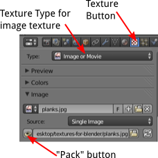
several images that you can use as image textures (or find your own). When you add a new texture to an object
and set the texture type to "Image or Movie", the "Image" section will have an "Open" button
that you can use to select a file to use for the texture. (The button will be replaced
by the name of the file.)
The folder /classes/cs424/textures-for-blender contains
several images that you can use as image textures (or find your own). When you add a new texture to an object
and set the texture type to "Image or Movie", the "Image" section will have an "Open" button
that you can use to select a file to use for the texture. (The button will be replaced
by the name of the file.)
Ordinarily, the .blend file just contains the path to the file, so that if you move the .blend file, you have to move the file along with it. To fix this, go to "File" menu / "External Data", and select "Automatically Pack into .blend". When this option is selected, Blender will save copies of any image textures in the .blend file, making it independent of the original image files. For this lab, if you only use images directly from the above folder, they do not have to be packed into the .blend file; however, if you use your own image files, they should be. (Note: You can make it easier to get to the images by setting the "File Path" for "Textures" in the "File" section of the User Preferences, which you can access from the "File" menu in Blender.)
Cool Stuff!
 The sample image demonstrates some cool effects that are difficult or impossible in OpenGL 1.1:
shadows, reflection, and transparency. Blender uses a ray tracer to render those effects.
(Note that these effects, as well as textures, are visible only in the rendered image, not in the
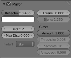
preview that you see in the Blender window.) For a reflective object, like the cylinder in the
image, you need to turn on the "Mirror" option in the Material controls for the object.
You also need to set the "Reflectivity" to be a non-zero value, since the default will still give a
non-reflective surface. The higher the reflectivity, the more reflective the surface.
The reflection of the environment is combined with the material color. The cylinder uses a
gold-colored material.
The sample image demonstrates some cool effects that are difficult or impossible in OpenGL 1.1:
shadows, reflection, and transparency. Blender uses a ray tracer to render those effects.
(Note that these effects, as well as textures, are visible only in the rendered image, not in the
preview that you see in the Blender window.) For a reflective object, like the cylinder in the
image, you need to turn on the "Mirror" option in the Material controls for the object.
You also need to set the "Reflectivity" to be a non-zero value, since the default will still give a
non-reflective surface. The higher the reflectivity, the more reflective the surface.
The reflection of the environment is combined with the material color. The cylinder uses a
gold-colored material.
![]() Transparent objects are similar. You need to turn on the "Transparency" option in the Material
controls for the object. Set the type of transparency to "Raytrace". Again, you need to change
the default value of "Alpha" to actually make a transparent object. The sphere uses a small
alpha value to get a highly transparent object. The larger value for "Specular" allows the
sphere to still have distinct, not quite so transparent, specular highlights.
I also set the "IOR" to be a value very slightly
greater than 1. IOR stands for "index of refraction," and a value other than one makes
the object look like it bends the light rays that pass through it.
(By the way, shadows of transparent objects will, by default, be just as dark as if
the object were opaque. The fix that, you need to go to the Material controls for the objects
on which the shadow falls. In the "Shadow" section, turn on the option "Receive Transparent")
Transparent objects are similar. You need to turn on the "Transparency" option in the Material
controls for the object. Set the type of transparency to "Raytrace". Again, you need to change
the default value of "Alpha" to actually make a transparent object. The sphere uses a small
alpha value to get a highly transparent object. The larger value for "Specular" allows the
sphere to still have distinct, not quite so transparent, specular highlights.
I also set the "IOR" to be a value very slightly
greater than 1. IOR stands for "index of refraction," and a value other than one makes
the object look like it bends the light rays that pass through it.
(By the way, shadows of transparent objects will, by default, be just as dark as if
the object were opaque. The fix that, you need to go to the Material controls for the objects
on which the shadow falls. In the "Shadow" section, turn on the option "Receive Transparent")
 You are required to do something with
Edit Mode.
In the sample image, the heart that is leaning against the back wall was made by
modifying a "NURBS Sphere" in Edit Mode. (A NURBS surface is something like a Bezier curve,
in that it has control points that influence the shape of the surface but do not lie on the surface. In Edit mode, you
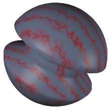
can reshape the surface by modifying the positions of the control points). The shape shown
here,
on the right, was made by editing a UV Sphere. To make it, I put the sphere into edit mode,
deselected all the vertices (with the A key), selected a band of vertices around the
equator (using box select with the B key), and then scaled down the selected vertices
(using the G key).
You are required to do something with
Edit Mode.
In the sample image, the heart that is leaning against the back wall was made by
modifying a "NURBS Sphere" in Edit Mode. (A NURBS surface is something like a Bezier curve,
in that it has control points that influence the shape of the surface but do not lie on the surface. In Edit mode, you
can reshape the surface by modifying the positions of the control points). The shape shown
here,
on the right, was made by editing a UV Sphere. To make it, I put the sphere into edit mode,
deselected all the vertices (with the A key), selected a band of vertices around the
equator (using box select with the B key), and then scaled down the selected vertices
(using the G key).
Next week's Blender lab will concentrate on more advanced modeling. You should read Section B.2 before then.