Section 5.2
Building Objects
In three.js, a visible object is constructed from a geometry and a material. We have seen how to create simple geometries that are suitable for point and line primitives, and we have encountered a variety of standard mesh geometries, such as THREE.CylinderGeometry and THREE.IcosahedronGeometry, that use the GL_TRIANGLES primitive. In this section, we will see how to create new mesh geometries from scratch. We'll also look at some of the other support that three.js provides for working with objects and materials.
5.2.1 Polygonal Meshes and IFSs
A mesh in three.js is what we called a polygonal mesh in Section 3.4, although in a three.js mesh, all of the polygons must be triangles. There are two ways to draw polygonal meshes in WebGL. One uses the function glDrawArrays(), which requires just a list of vertices. The other uses the representation that we called an indexed face set (IFS), which is drawn using the function glDrawElements(). In addition to a list of vertices, an IFS uses a list of face indices to specify the triangles. We will look at both methods, using this pyramid as an example:
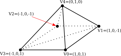
Note that the bottom face of the pyramid, which is a square, has to be divided into two triangles in order for the pyramid to be represented as a mesh geometry. The vertices are numbered from 0 to 4. A triangular face can be specified by the three numbers that give the vertex numbers of the vertices of that triangle. As usual, the vertices of a triangle should be specified in counterclockwise order when viewed from the front, that is, from outside the pyramid. Here is the data that we need.
      VERTEX COORDINATES:         FACE INDICES:

      Vertex 0:   1, 0,  1        Face 1:  3, 2, 1
      Vertex 1:   1, 0, -1        Face 2:  3, 1, 0
      Vertex 2:  -1, 0, -1        Face 3:  3, 0, 4
      Vertex 3:  -1, 0,  1        Face 4:  0, 1, 4
      Vertex 4:   0, 1,  0        Face 5:  1, 2, 4
                                  Face 6:  2, 3, 4
A basic polygonal mesh representation does not use face indices. Instead, it specifies each triangle by listing the coordinates of the vertices. This requires nine numbers—three numbers per vertex—for the three vertices of the triangle. Since a vertex can be shared by several triangles, there is some redundancy. For the pyramid, the coordinates for a vertex will be repeated three or four times.
A three.js mesh object requires a geometry and a material. The geometry is an object of type THREE.BufferedGeometry, which has a "position" attribute that holds the coordinates of the vertices that are used in the mesh. The attribute uses a typed array that holds the coordinates of the vertices of the triangles that make up the mesh. Geometry for the pyramid can be created like this:
let pyramidVertices = new Float32Array( [
               // Data for the pyramidGeom "position" attribute.
               // Contains the x,y,z coordinates for the vertices.
               // Each group of three numbers is a vertex;
               // each group of three vertices is one face.
            -1,0,1,  -1,0,-1,  1,0,-1, // First triangle in the base.
            -1,0,1,   1,0,-1,  1,0,1,  // Second triangle in the base.
            -1,0,1,   1,0,1,   0,1,0,  // Front face.
             1,0,1,   1,0,-1,  0,1,0,  // Right face.
             1,0,-1, -1,0,-1,  0,1,0,  // Back face.
            -1,0,-1, -1,0,1,   0,1,0   // Left face.
        ] );
let pyramidGeom = new THREE.BufferGeometry();
pyramidGeom.setAttribute("position",
                new THREE.BufferAttribute(pyramidVertices,3) );
When this geometry is used with a Lambert or Phong material, normal vectors are required for the vertices. If the geometry has no normal vectors, Lambert and Phong materials will appear black. The normal vectors for a mesh have to be stored in another attribute of the BufferedGeometry. The name of the attribute is "normal", and it holds a normal vector for each vertex in the "position" attribute. It could be created in the same way that the "position" attribute is created, but a BufferedGeometry object includes a method for calculating normal vectors. For the pyramidGeom, we can simply call
pyramidGeom.computeVertexNormals();
For a basic polygonal mesh, this will create normal vectors that are perpendicular to the faces. When several faces share a vertex, that vertex will have a different normal vector for each face. This will produce flat-looking faces, which are appropriate for a polyhedron, whose sides are in fact flat. It is not appropriate if the polygonal mesh is being used to approximate a smooth surface. In that case, we should be using normal vectors that are perpendicular to the surface, which would mean creating the "normal" attribute by hand. (See Subsection 4.1.3.)
Once we have the geometry for our pyramid, we can use it in a three.js mesh object by combining it with, say, a yellow Lambert material:
pyramid = new THREE.Mesh(
             pyramidGeom,
             new THREE.MeshLambertMaterial({ color: "yellow" })
          );
But the pyramid would look a little boring with just one color. It is possible to use different materials on different faces of a mesh. For that to work, the vertices in the geometry must be divided into groups. The addGroup() method in the BufferedGeometry class is used to create the groups. The vertices in the geometry are numbered 0, 1, 2, ..., according their sequence in the "position" attribute. (This is not the same numbering used above.) The addGroup() method takes three parameters: the number of the first vertex in the group, the number of vertices in the group, and a material index. The material index is an integer that determines which material will be applied to the group. If you are using groups, it is important to put all of the vertices into groups. Here is how groups can be created for the pyramid:
pyramidGeom.addGroup(0,6,0);  // The base (2 triangles)
pyramidGeom.addGroup(6,3,1);  // Front face.
pyramidGeom.addGroup(9,3,2);  // Right face.
pyramidGeom.addGroup(12,3,3); // Back face.
pyramidGeom.addGroup(15,3,4); // Left face.
To apply different materials to different groups, the materials should be put into an array. The material index of a group is an index into that array.
pyramidMaterialArray= [
           // Array of materials, for use as pyramids's material.
        new THREE.MeshLambertMaterial( { color: 0xffffff } ),
        new THREE.MeshLambertMaterial( { color: 0x99ffff } ),
        new THREE.MeshLambertMaterial( { color: 0xff99ff } ),
        new THREE.MeshLambertMaterial( { color: 0xffff99 } ),
        new THREE.MeshLambertMaterial( { color: 0xff9999 } )
    ];
This array can be passed as the second parameter to the THREE.Mesh constructor, where a single material would ordinarily be used.
pyramid = new THREE.Mesh( pyramidGeom, pyramidMaterialArray );
(But note that you can still use a single material on a mesh, even if the mesh geometry uses groups.)
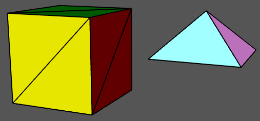
A THREE.BoxGeometry comes with groups that make it possible to assign a different material to each face. The sample program threejs/vertex-groups.html uses the code from this section to create a pyramid, and it displays both the pyramid and a cube, using multiple materials on each object. Here's what they look like:
There is another way to assign different colors to different vertices. A BufferedGeometry can have an attribute named "color" that specifies a color for each vertex. The "color" attribute uses an array containing a set of three RGB component values for each vertex. The vertex colors are ignored by default. To use them, the geometry must be combined with a material in which the vertexColors property is set to true. Here is how vertex colors could be used to color the sides of the pyramid:
pyramidGeom.setAttribute(
         "color",
         new THREE.BufferAttribute( new Float32Array([
                  1,1,1,  1,1,1,  1,1,1, // Base vertices are white
                  1,1,1,  1,1,1,  1,1,1,
                  1,0,0,  1,0,0,  1,0,0, // Front face vertices are red,
                  0,1,0,  0,1,0,  0,1,0, // Right face vertices are green,
                  0,0,1,  0,0,1,  0,0,1, // Back face vertices are blue,
                  1,1,0,  1,1,0,  1,1,0  // Left face vertices are yellow.
               ]), 3)
      );
pyramid = new THREE.Mesh(
        pyramidGeom,
        new THREE.MeshLambertMaterial({
              color: "white",
              vertexColors: true
         })
      );
The color components of the vertex colors from the geometry are actually multiplied by the color components of the color in the Lambert material. It makes sense for that color to be white, with color components equal to one; in that case the vertex colors are not modified by the material color.
In this example, each face of the pyramid is a solid color. There is a lot of redundancy in the color array for the pyramid, because a color must be specified for every vertex, even if all of the vertex colors for a given face are the same. In fact, it's not required that all of the vertices of a face have the same color. If they are assigned different colors, colors will be interpolated from the vertices to the interior of the face. As an example, in the following demo, a random vertex color was specified for each vertex of an icosahedral approximation for a sphere:
The demo can run two somewhat silly animations; the vertex colors and the vertex positions can be animated.
The glDrawElements() function is used to avoid the redundancy of the basic polygonal mesh representation. It uses the indexed face set pattern, which requires an array of face indices to specify the vertices for the faces of the mesh. In that array, a vertex is specified by a single number, rather than repeating all of the coordinates and other data for that vertex. Note that a given vertex number refers to all of the data for that vertex: vertex coordinates, normal vector, vertex color, and any other data that are provided in attributes of the geometry. Suppose that two faces share a vertex. If that vertex has a different normal vector, or a different value for some other attribute, in the two faces, then that vector will need to occur twice in the attribute arrays. The two occurrences can be combined only if the vertex has identical properties in the two faces. The IFS representation is most suitable for a polygonal mesh that is being used as an approximation for a smooth surface, since in that case a vertex has the same normal vector for all of the vertices in which it occurs. It can also be appropriate for an object that uses a MeshBasicMaterial, since normal vectors are not used with that type of material.
To use the IFS pattern with a BufferedGeometry, you need to provide a face index array for the geometry. The array is specified by the geometry's setIndex() method. The parameter can be an ordinary JavaScript array of integers. For our pyramid example the "position" attribute of the geometry would contain each vertex just once, and the face index array would refer to a vertex by its position in that list of vertices:
pyramidVertices = new Float32Array( [
             1, 0,  1,  // vertex number 0
             1, 0, -1,  // vertex number 1
            -1, 0, -1,  // vertex number 2
            -1, 0,  1,  // vertex number 3
             0, 1,  0   // vertex number 4
   ] );

pyramidFaceIndexArray = [
            3, 2, 1,  // First triangle in the base.
            3, 1, 0,  // Second Triangle in the base.
            3, 0, 4,  // Front face.
            0, 1, 4,  // Right face.
            1, 2, 4,  // Back face.
            2, 3, 4   // Left face.
   ];

pyramidGeom = new THREE.BufferGeometry();
pyramidGeom.setAttribute("position",
                new THREE.BufferAttribute(pyramidVertices,3) );
pyramidGeom.setIndex( pyramidFaceIndexArray );
This would work with a MeshBasicMaterial. The sample program threejs/vertex-groups-indexed.html is a variation on threejs/vertex-groups.html that uses this approach.
The computeVertexNormals() method can still be used for a BufferedGeometry that has an index array. To compute a normal vector for a vertex, it finds all of the faces in which that vertex occurs. For each of those faces, it computes a vector perpendicular to the face. Then it averages those vectors to get the vertex normal. (I will note if you tried this for our pyramid, it would look pretty bad. It's really only appropriate for smooth surfaces.)
5.2.2 Curves and Surfaces
In addition to letting you build indexed face sets, three.js has support for working with curves and surfaces that are defined mathematically. Some of the possibilities are illustrated in the sample program threejs/curves-and-surfaces.html, and I will discuss a few of them here.
Parametric surfaces are the easiest to work with. They are represented by a three.js add-on named ParametricGeometry. As an add-on, it must be imported separately from the main three.js module. In my sample program, it is imported with
import {ParametricGeometry} from "addons/geometries/ParametricGeometry.js";
A parametric surface is defined by a mathematical function of two parameters (u,v), where u and v are numbers, and each value of the function is a point in space. The surface consists of all the points that are values of the function for u and v in some specified ranges. For three.js, the function is a regular JavaScript function that takes three parameters: u, v, and an object of type THREE.Vector3. The function must modify the vector to represent the point in space that corresponds to the values of the u and v parameters. A parametric surface geometry is created by calling the function at a grid of (u,v) points. This gives a collection of points on the surface, which are then connected to give a polygonal approximation of the surface. In three.js, the values of both u and v are always in the range 0.0 to 1.0. The geometry is created by a constructor
new ParametricGeometry( func, slices, stacks )
where func is the JavaScript function that defines the surface, and slices and stacks determine the number of points in the grid; slices gives the number of subdivisions of the interval from 0 to 1 in the u direction, and stacks, in the v direction. Once you have the geometry, you can use it to make a mesh in the usual way. Here is an example, from the sample program:
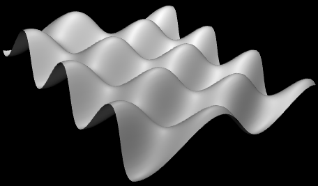
This surface is defined by the function
function surfaceFunction( u, v, vector ) {
    let x,y,z;  // Coordinates for a point on the surface,
                // calculated from u,v, where u and v
                // range from 0.0 to 1.0.
    x = 20 * (u - 0.5);  // x and z range from -10 to 10
    z = 20 * (v - 0.5);
    y = 2*(Math.sin(x/2) * Math.cos(z));
    vector.set( x, y, z );
}
and the three.js mesh that represents the surface is created using
let surfaceGeometry = new THREE.ParametricGeometry(surfaceFunction, 64, 64);
let surface = new THREE.Mesh( surfaceGeometry, material );
Curves are more complicated in three.js. The class THREE.Curve represents the abstract idea of a parametric curve in two or three dimensions. (It does not represent a three.js geometry.) A parametric curve is defined by a function of one numeric variable t. The value returned by the function is of type THREE.Vector2 for a 2D curve or THREE.Vector3 for a 3D curve. For an object, curve, of type THREE.Curve, the method curve.getPoint(t) should return the point on the curve corresponding to the value of the parameter t. The curve consists of points generated by this function for values of t ranging from 0.0 to 1.0. However, in the Curve class itself, getPoint() is undefined. To get an actual curve, you have to define it. For example,
let helix = new THREE.Curve();
helix.getPoint = function(t) {
   let s = (t - 0.5) * 12*Math.PI;
         // As t ranges from 0 to 1, s ranges from -6*PI to 6*PI
   return new THREE.Vector3(
        5*Math.cos(s),
        s,
        5*Math.sin(s)
   );
}
Once getPoint is defined, you have a usable curve. One thing that you can do with it is create a tube geometry, which defines a surface that is a tube with a circular cross-section and with the curve running along the center of the tube. The sample program uses the helix curve, defined above, to create two tubes:
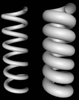
The geometry for the wider tube is created with
tubeGeometry1 = new THREE.TubeGeometry( helix, 128, 2.5, 32 );
The second parameter to the constructor is the number of subdivisions of the surface along the length of the curve. The third is the radius of the circular cross-section of the tube, and the fourth is the number of subdivisions around the circumference of the cross-section.
To make a tube, you need a 3D curve. There are also several ways to make a surface from a 2D curve. One way is to rotate the curve about a line, generating a surface of rotation. The surface consists of all the points that the curve passes through as it rotates. This is called lathing. This image from the sample program shows the surface generated by lathing a cosine curve. (The image is rotated 90 degrees, so that the y-axis is horizontal.) The curve itself is shown above the surface:
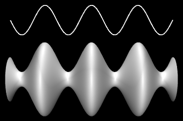
The surface is created in three.js using a THREE.LatheGeometry object. A LatheGeometry is constructed not from a curve but from an array of points that lie on the curve. The points are objects of type Vector2, and the curve lies in the xy-plane. The surface is generated by rotating the curve about the y-axis. The LatheGeometry constructor takes the form
new THREE.LatheGeometry( points, slices )
The first parameter is the array of Vector2. The second is the number of subdivisions of the surface along the circle generated when a point is rotated about the axis. (The number of "stacks" for the surface is given by the length of the points array.) In the sample program, I create the array of points from an object, cosine, of type Curve by calling cosine.getPoints(128). This function creates an array of 128 points on the curve, using values of the parameter that range from 0.0 to 1.0.
Another thing that you can do with a 2D curve is simply to fill in the inside of the curve, giving a 2D filled shape. To do that in three.js, you can use an object of type THREE.Shape, which is a subclass of THREE.Curve. A Shape can be defined in the same way as a path in the 2D Canvas API that was covered in Section 2.6. That is, an object shape of type THREE.Shape has methods shape.moveTo, shape.lineTo, shape.quadraticCurveTo and shape.bezierCurveTo that can be used to define the path. See Subsection 2.6.2 for details of how these functions work. As an example, we can create a teardrop shape:
let path = new THREE.Shape();
path.moveTo(0,10);
path.bezierCurveTo( 0,5, 20,-10, 0,-10 );
path.bezierCurveTo( -20,-10, 0,5, 0,10 );
To use the path to create a filled shape in three.js, we need a ShapeGeometry object:
let shapeGeom = new THREE.ShapeGeometry( path );
The 2D shape created with this geometry is shown on the left in this picture:
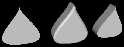
The other two objects in the picture were created by extruding the shape. In extrusion, a filled 2D shape is moved along a path in 3D. The points that the shape passes through make up a 3D solid. In this case, the shape was extruded along a line segment perpendicular to the shape, which is the most common case. The basic extruded shape is shown on the right in the illustration. The middle object is the same shape with "beveled" edges. For more details on extrusion, see the documentation for THREE.ExtrudeGeometry and the source code for the sample program.
5.2.3 Textures
A texture can be used to add visual interest and detail to an object. In three.js, an image texture is represented by an object of type THREE.Texture. Since we are talking about web pages, the image for a three.js texture is generally loaded from a web address. Image textures are usually created using the load function in an object of type THREE.TextureLoader. The function takes a URL (a web address, usually a relative address) as parameter and returns a Texture object:
let loader = new THREE.TextureLoader();
let texture = loader.load( imageURL );
(It is also advisable to set
tex.colorSpace = THREE.SRGBColorSpace;
to display the colors correctly. The three.js documentation says, "PNG or JPEG Textures containing color information (like .map or .emissiveMap) use the closed domain sRGB color space, and must be annotated with texture.colorSpace = SRGBColorSpace.")
A texture in three.js is considered to be part of a material. To apply a texture to a mesh, just assign the Texture object to the map property of the mesh material that is used on the mesh:
material.map = texture;
The map property can also be set in the material constructor. All three types of mesh material (Basic, Lambert, and Phong) can use a texture. In general, the material base color will be white, since the material color will be multiplied by colors from the texture. A non-white material color will add a "tint" to the texture colors. The texture coordinates that are needed to map the image to a mesh are part of the mesh geometry. The standard mesh geometries such as THREE.SphereGeometry come with texture coordinates already defined.
That's the basic idea—create a texture object from an image URL and assign it to the map property of a material. However, there are complications. First of all, image loading is "asynchronous." That is, calling the load function only starts the process of loading the image, and the process can complete sometime after the function returns. Using a texture on an object before the image has finished loading does not cause an error, but the object will be rendered as completely black. Once the image has been loaded, the scene has to be rendered again to show the image texture. If an animation is running, this will happen automatically; the image will appear in the first frame after it has finished loading. But if there is no animation, you need a way to render the scene once the image has loaded. In fact, the load function in a TextureLoader has several optional parameters:
loader.load( imageURL, onLoad, undefined, onError );
The third parameter here is given as undefined because that parameter is no longer used. The onLoad and onError parameters are callback functions. The onLoad function, if defined, will be called once the image has been successfully loaded. The onError function will be called if the attempt to load the image fails. For example, if there is a function render() that renders the scene, then render itself could be used as the onLoad function:
texture = new THREE.TextureLoader().load( "brick.png", render );
Another possible use of onLoad would be to delay assigning the texture to a material until the image has finished loading. If you do add the texture later, be sure to set
material.needsUpdate = true;
to make sure that the change will take effect when the object is redrawn. (When exactly needsUpdate needs to be set on various objects is not always clear. See the "Updating Resources" section of the three.js documentation.)
A Texture has a number of properties that can be set, including properties to set the minification and magnification filters for the texture and a property to control the generation of mipmaps, which is done automatically by default. The properties that you are most likely to want to change are the wrap mode for texture coordinates outside the range 0 to 1 and the texture transformation. (See Section 4.3 for more information about these properties.)
For a Texture object tex, the properties tex.wrapS and tex.wrapT control how s and t texture coordinates outside the range 0 to 1 are treated. The default is "clamp to edge." You will most likely want to make the texture repeat in both directions by setting the property values to THREE.RepeatWrapping:
tex.wrapS = THREE.RepeatWrapping;
tex.wrapT = THREE.RepeatWrapping;
RepeatWrapping works best with "seamless" textures, where the top edge of the image matches up with the bottom edge and the left edge with the right. Three.js also offers an interesting variation called "mirrored repeat" in which every other copy of the repeated image is flipped. This eliminates the seam between copies of the image. For mirrored repetition, use the property value THREE.MirroredRepeatWrapping:
tex.wrapS = THREE.MirroredRepeatWrapping;
tex.wrapT = THREE.MirroredRepeatWrapping;
The texture properties repeat, offset, and rotation control the scaling, translation, and rotation that are applied to the texture as texture transformations. The values of repeat and offset are of type THREE.Vector2, so that each property has an x and a y component. The rotation is a number, measured in radians, giving the rotation of the texture about the point (0,0). (But the center of rotation is actually given by another property named center.) For a Texture, tex, the two components of tex.offset give the texture translation in the horizontal and vertical directions. To offset the texture by 0.5 horizontally, you can say either
tex.offset.x = 0.5;
or
tex.offset.set( 0.5, 0 );
Remember that a positive horizontal offset will move the texture to the left on the objects, because the offset is applied to the texture coordinates not to the texture image itself.
The components of the property tex.repeat give the texture scaling in the horizontal and vertical directions. For example,
tex.repeat.set(2,3);
will scale the texture coordinates by a factor of 2 horizontally and 3 vertically. Again, the effect on the image is the inverse, so that the image is shrunk by a factor of 2 horizontally and 3 vertically. The result is that you get two copies of the image in the horizontal direction where you would have had one, and three vertically. This explains the name "repeat," but note that the values are not limited to be integers.
This demo lets you view some textured three.js objects. The "Pill" object in the demo, by the way, is a compound object consisting of a cylinder and two hemispheres.
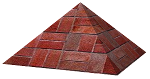
Suppose that we want to use an image texture on the pyramid that was created at the beginning of this section. In order to apply a texture image to an object, WebGL needs texture coordinates for that object. When we build a mesh from scratch, we have to supply the texture coordinates as part of the mesh's geometry object.
Let's see how to do this on our pyramid example. A BufferedGeometry object such as pyramidGeom in the example has an attribute named "uv" to hold texture coordinates. (The name "uv" refers to the coordinates on an object that are mapped to the s and t coordinates in a texture. The texture coordinates for a surface are often referred to as "uv coordinates.") The BufferAttribute for a "uv" attribute can be made from a typed array containing a pair of texture coordinates for each vertex.
Our pyramid example has six triangular faces, with a total of 18 vertices. We need an array containing vertex coordinates for 18 vertices. The coordinates have to be chosen to map the image in a reasonable way onto the faces. My choice of coordinates maps the entire texture image onto the square base of the pyramid, and it cuts a triangle out of the image to apply to each of the sides. It takes some care to come up with the correct coordinates. I define the texture coordinates for the pyramid geometry as follows:
let pyramidUVs = new Float32Array([
         0,0,  0,1,  1,1,   // uv coords for first triangle in base.
         0,0,  1,1,  1,0,   // uv coords for second triangle in base.
         0,0,  1,0,  0.5,1, // uv coords for front face.
         1,0,  0,0,  0.5,1, // uv coords for right face.
         0,0,  1,0,  0.5,1, // uv coords for back face.
         1,0,  0,0,  0.5,1  // uv coords for left face.
]);
pyramidGeom.setAttribute("uv",
                         new THREE.BufferAttribute(pyramidUVs,2) );
The sample program threejs/textured-pyramid.html shows the pyramid with a brick texture. Here is an image from the program:
5.2.4 Transforms
In order to understand how to work with objects effectively in three.js, it can be useful to know more about how it implements transforms. I have explained that an Object3D, obj, has properties obj.position, obj.scale, and obj.rotation that specify its modeling transformation in its own local coordinate system. But these properties are not used directly when the object is rendered. Instead, they are combined to compute another property, obj.matrix, that represents the transformation as a matrix. By default, this matrix is recomputed automatically every time the scene is rendered. This can be inefficient if the transformation never changes, so obj has another property, obj.matrixAutoUpdate, that controls whether obj.matrix is computed automatically. If you set obj.matrixAutoUpdate to false, the update is not done. In that case, if you do want to change the modeling transformation, you can call obj.updateMatrix() to compute the matrix from the current values of obj.position, obj.scale, and obj.rotation.
We have seen how to modify obj's modeling transformation by directly changing the values of the properties obj.position, obj.scale, and obj.rotation. However, you can also change the position by calling the function obj.translateX(dx), obj.translateY(dy), or obj.translateZ(dz) to move the object by a specified amount in the direction of a coordinate axis. There is also a function obj.translateOnAxis(axis,amount), where axis is a Vector3 and amount is a number giving the distance to translate the object. The object is moved in the direction of the vector, axis. The vector must be normalized; that is, it must have length 1. For example, to translate obj by 5 units in the direction of the vector (1,1,1), you could say
obj.translateOnAxis( new THREE.Vector3(1,1,1).normalize(), 5 );
There are no functions for changing the scaling transform. But you can change the object's rotation with the functions obj.rotateX(angle), obj.rotateY(angle), and obj.rotateZ(angle) to rotate the object about the coordinate axes. (Remember that angles are measured in radians.) Calling obj.rotateX(angle) is not the same as adding angle onto the value of obj.rotation.x, since it applies a rotation about the x-axis on top of other rotations that might already have been applied.
There is also a function obj.rotateOnAxis(axis,angle), where axis is a Vector3. This function rotates the object through the angle angle about the vector (that is, about the line between the origin and the point given by axis). The axis must be a normalized vector.
(Rotation is actually even more complicated. The rotation of an object, obj, is actually represented by the property obj.quaternion, not by the property obj.rotation. Quaternions are mathematical objects that are often used in computer graphics as an alternative to Euler angles, to represent rotations. However, when you change one of the properties obj.rotation or obj.quaternion, the other is automatically updated to make sure that both properties represent the same rotation. So, we don't need to work directly with the quaternions.)
I should emphasize that the translation and rotation functions modify the position and rotation properties of the object. That is, they apply in object coordinates, not world coordinates, and they are applied as the first modeling transformation on the object when the object is rendered. For example, a rotation in world coordinates can change the position of an object, if it is not positioned at the origin. However, changing the value of the rotation property of an object will never change its position.
The actual transformation that is applied to an object when it is rendered is a combination of the modeling transformation of that object, combined with the modeling transformation on all of its ancestors in the scene graph. In three.js, that transformation is stored in a property of the object named obj.matrixWorld.
There is one more useful method for setting the rotation: obj.lookAt(vec), which rotates the object so that it is facing towards a given point. The parameter, vec, is a Vector3, which must be expressed in the object's own local coordinate system. (For an object that has no parent, or whose ancestors have no modeling transformations, that will be the same as world coordinates.) The object is also rotated so that its "up" direction is equal to the value of the property obj.up, which by default is (0,1,0). This function can be used with any object, but it is most useful for a camera.
5.2.5 Loading Models
Although it is possible to create mesh objects by listing their vertices and faces, it would be difficult to do it by hand for all but very simple objects. It's much easier, for example, to design an object in an interactive modeling program such as Blender (Appendix B). Modeling programs like Blender can export objects using many different file formats. Three.js has utility functions for loading models from files in a variety of file formats. These utilities are not part of the three.js core, but JavaScript files that define them can be found in the examples folder in the three.js download.
The preferred format for model files is GLTF. A GLTF model can be stored in a text file with extension .gltf or in a binary file with extension .glb. Binary files are smaller and more efficient, but not human-readable. A three.js loader for GLTF files is defined by the class GLTFLoader, which can be imported from the module GLTFLoader.js. from the three.js download. Copies of that script, as well as scripts for other model loaders, can be found in the threejs/script/loaders folder in the source folder for this textbook, or in the examples/jsm/loaders folder in the three.js download. (Note that GLTFLoader is not part of the object THREE.)
If loader is an object of type GLTFLoader, you can use its load() method to start the process of loading a model:
loader = new GLTFLoader()
loader.load( url, onLoad, onProgress, onError );
Only the first parameter is required; it is a URL for the file that contains the model. The other three parameters are callback functions: onLoad will be called when the loading is complete, with a parameter that represents the data from the file; onProgress is called periodically during the loading with a parameter that contains information about the size of the model and how much of it has be loaded; and onError is called if any error occurs. (I have not actually used onProgress myself.) Note that, as for textures, the loading is done asynchronously.
A GLTF file can be quite complicated and can contain an entire 3D scene, containing multiple objects, lights, and other things. The data returned by a GLTFLoader contains a three.js Scene. Any objects defined by the file will be part of the scene graph for that scene. All of the model files used in this textbook define a Mesh object that is the first child of the Scene object. This object comes complete with both geometry and material. The onLoad callback function can add that object to the scene and might look something like this:
function onLoad(data) { // the parameter is the loaded model data
    let object = data.scene.children[0];
    // maybe modify the modeling transformation or material...
    scene.add(object);  // add the loaded object to our scene
    render();  // call render to show the scene with the new object
}
The sample program threejs/model-viewer.html uses GLTFLoader to load several models. It also uses loaders for models in two other formats, Collada and OBJ, that work much the same way. The technique for loading the models is actually a little more general that what I've described here. See the source code for the example program for details.
I'll also mention that GLTF models can include animations. Three.js has several classes that support animation, including THREE.AnimationMixer, THREE.AnimationAction, and THREE.AnimationClip. I won't discuss animation here, but these three classes are used to animate the horse and stork models in this demo: